Introduction:
The actual project used on this page involved replacing two existing pre-cast concrete crown units and covers with trays in preparation for the driveway being re-constructed using concrete block paving. However, the type of surfacing or paving that is to be used is irrelevant - what matters is how the new recess tray is fitted.
Thanks are due to Alan Moore of Penketh, Warrington for granting permission to use his driveway for this illustration.
Breaking-out
On this job, existing covers will be replaced. For projects where a new manhole or inspection chamber is to be fitted with a recess tray cover, this section may be omitted and work starts at the next section: Build-Up
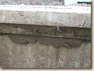
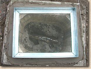
The type of cover that will be replaced is shown opposite. This is known as a "pre-cast concrete crown unit and cover" and they are manufactured from a relatively strong concrete with some mild steel reinforcement. They were popularly used on new house constructed between the mid 1960s right up until the early 1990s, when their supremacy was finally overhauled by Polypropylene chambers. They are still used today, although not in the sort of quantities that they once were.
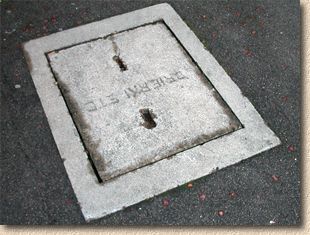
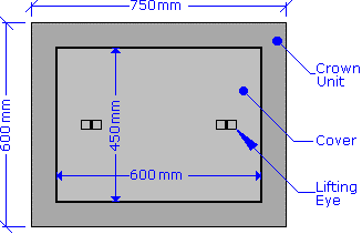
The whole unit has dimensions of, roughly, 750mm x 600mm, although the cover itself (the 'lid') is only 600x450mm. It's worth noting that there is some variation in size between the various manufacturers, but that the key point at this stage is to note the dimensions of the cover which sits within the crown unit, so that an equivalent sized recess tray unit can be purchased from the local supplier (usually a Builder's or Civils Merchant).
Note also the lifting eyes. These usually comprise a steel bar cast into a a small rebated area of the cover. In many cases, the rebate is filled with accumulated detritus and/or the steel bar has rusted away to nothing. If the lifting eyes are not suitable for use, then the cover will have to be removed by other means.
However, at this stage, the cover, and indeed the crown unit itself, should be left in place.
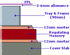
The first task is to determine the finished paving level (FPL). This can be established by using a taut string line stretched between two known points. The whys and wherefores of establishing paving levels is covered in the Setting Out section of this website.
The purpose of establishing the FPL is to determine whether the replacement recess tray can be seated directly into the existing crown unit, whether it will require 'packing' to lift it to an elevated level, or whether it will require 'dropping' to suit the FPL. This is done by measuring the depth of the tray (and its frame) and comparing this to the difference between FPL and existing Cover Level (CL).
Let's assume the tray and frame have an overall depth of 90mm. We need to allow a minimum of 10mm for mortar bedding, so, if the FPL is 100mm or higher than the current CL, then the existing Crown Unit can be used to carry the recess tray and frame. In some cases, the frame of the recess tray will fit quite snugly into the rebate of the crown unit and sit on the flange used to carry the original concrete cover. However, not many of us have this sort of luck, and so the recess tray frame usually has to sit uncomfortably on the crown unit.
In many cases, the CL is at, or not far off, the required FPL, and as the tray and frame require a clear 100mm between CL and FPL to be fitted, the existing Crown Unit will have to be removed and dropped in level to accommodate the tray.
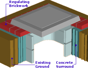
This is achieved by removing the crown unit, removing any regulating brickwork or the top chamber section beneath the crown unit, replacing the crown unit and then fixing the new recess tray and frame on top the top of the crown unit. This detailed more fully below.
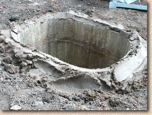
The first task is to excavate around the crown unit to expose it. The cover should be left in place to prevent any spoil falling into the chamber during the excavation works.
The excavation should continue all around the chamber to expose any course(s) of regulating brickwork that may be present. Alternatively, if no regulating brickwork is present, then the topmost chamber section should be fully exposed. The excavation should be wide enough to provide adequate working room, which usually means one spade width (roughly 250-300mm), and the ground should be reduced to until it is slightly lower, say 25-30mm, that the top of the underlying chamber section. This helps prevent any debris falling into the chamber when the crown unit, regulating brickwork and/or chamber sections are removed.
In some situations, the regulating brickwork and/or the chamber sections will be surrounded by concrete. This is not a common occurrence but it is an approved construction and some chambers, most notably those that may have been 'adopted' by the local authority or those in bad ground, will have been constructed in this manner. While using a concrete surround makes for a wonderful manhole construction, it makes the breakout phase of this task immeasurably more difficult. Often the only viable option is to use a jack-hammer or powered breaker to break up the concrete, but great care is needed to ensure the breaker doesn't damage those parts of the chamber that need to remain intact.
Once the regulating brickwork/chamber section is exposed, the crown unit and cover can be removed. This is done by first removing the cover and then lifting the crown unit itself. This will be required in the later stages of this procedure so it should be set aside carefully. It should also be noted that a typical crown unit of this size will weigh something around 50kg and so it is better to have 2 persons to lift it or to use a digger/crane to lift the unit. In some cases, the crown unit will have been bedded on mortar, so it may be necessary to separate the two by driving a chisel or wrecker bar into the joint and so break the bond.
Following the removal of the crown unit and cover, any regulating brickwork can be taken down. A hammer and chisel may be required to break up the brickwork and care is required to minimise the amount of debris that can fall into the now-open chamber. It's best to chisel from the internal face of the brickwork, hammering the chisel towards the exterior of the chamber; doing it the other way increases the amount of smashed brickwork and crumbling mortar that will fall into the chamber.
In cases where the topmost chamber section has to be removed, this too may be mortar bedded and will need to be separated from the lower chamber sections. Hammering in a chisel at the joint between the sections is usually sufficient to free the topmost section, but, as this section will no longer be required, it could be broken in-situ by hitting with a sledgehammer or similar. Again, care should be taken to prevent debris falling into the chamber.
This is the end of the breakout phase. The chamber has been 'reduced' to a level which can accommodate the re-fitting of the Crown Unit plus the Tray and Frame. The next phase deals with the re-construction.
Build-Up
I - The Cover Slab
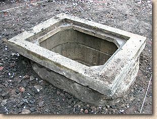
At this stage, the chamber has been taken down to formation level, that is, a level at which the re-construction work can commence.
The re-construction starts with the re-bedding of the Crown Unit, which will act as a cover slab . The Crown Unit is to be mortar bedded, which is done for two main reasons: Firstly, using a mortar bed eliminates the possibility of the Crown unit rocking when postioned on top of the chamber sections, and secondly; it helps ensure that the sub-base material and/or any bedding material that may be used with the subsequent paving can't be 'lost' or 'washed through' into the chamber.
For projects where there is no cover slab or crown unit to be salvaged and re-used, regulating masonry can be used in its place.
A Class II mortar should be used (roughly 4:1) with a plasticiser to improve workability. There is no need to add a waterproofer or a hardening agent. Reseating a Crown Unit of this size will use more or less a 'full-bag mix' of mortar - that is, a full, 25kg bag of building sand, with 6-8kg of cement (Sulphate Resistant [SRC] is best, but Ordinary Portland [OPC] will be satisfactory) along with water and plasticiser. The mortar is spread along the top of the chamber sections, and tidied along the internal edge to reduce the amount of mortar that will fall into the chamber when the Crown Unit is dropped into place.
As with the lifting of the Crown unit during the Breakdown, when it comes to re-placing it, great care is required, not only because of the weight of the Unit, and the fact that they tend to be cumbersome buggers, but also to prevent knocking off the bedding mortar into the chamber. It's a job for two operatives, or preferably a digger or other crane-capable piece of kit. Try to ensure the Crown Unit is evenly lowered onto the mortar bed, rather than drop one end in place then lowering the opposite end as though it were 'hinged'. This helps ensure the mortar bed isn't squeezed out at one end and left high at the other.
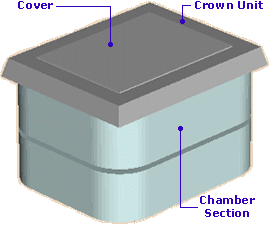
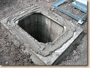
Note that the Crown Unit has been re-placed upside down. As the original cover is no longer needed, the rebated flange used to carry the cover is now redundant, and by inverting the Crown unit, the problem of getting mortar to sit in the rebate is eliminated, and a wider, even base is provided for subsequent build-up.
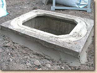
Note how mortar has been used to 'haunch' around the outside of the Crown Unit. This also serves two purposes: sealing the chamber against possible ingress of fines and silts, and simultaneously holding the Crown Unit securely in position. If necessary, the mortar haunch can be reinforced by adding a few spadefuls of concrete (C20 equivalent).
Also, if the chamber itself is not square with the pavement, then the Crown Unit can be skewed to some degree to correct this and, hopefully, once the build-up is complete, the tray cover itself will be square or conveniently aligned with the rest of the pavement. Obviously, there is a limit to how much of a 'skew' is possible. There should be no gaps between the re-placed Crown Unit and the chamber, but a skew of 10° - 15° is usually possible, and, if further skewing is required, this may be achieved by skewing the Tray and Frame in relation to the Crown Unit so that a total skew of 30° or more is possible.
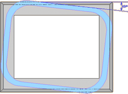
When the Crown Unit is placed on the mortar and tapped down to firmly bed it and eliminate any rocking, this often results in mortar being squeezed out on the inside of the chamber, as shown in the photo opposite. Left alone, this 'snot' of mortar will probably drop off while still plastic and fall to the base of the chamber - in fact, it's quite likely that, by now, there is already a quantity of mortar in the base of the chamber.
This joint should be tidied up by running a trowel or a pointing bar along the joint, trimming any excess mortar and sealing the joint in the process. Don't worry too much about mortar in the base of the chamber just yet: it will all be cleaned out when the task at hand is completed, but if there is a significant quantity of mortar down there, or it has fallen into the channel, then it should be cleaned out as soon as possible.
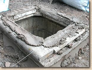
In some cases, pre-cast concrete reducing cover slabs can be used to reduce the manhole opening size. The reducing cover should be mortar bedded onto the existing manhole ring or brickwork, and 2-4 courses of 225mm wide Engineering brickwork used to establish finished level.
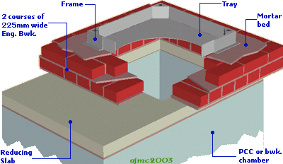
In the example shown here, a 1200x750mm chamber has been reduced by means of a cover slab so that a standard 600x600mm tray and frame can be fitted.
II - Regulating
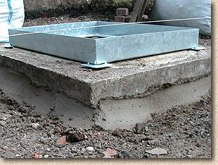
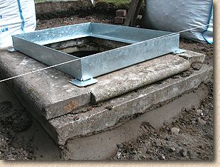
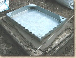
At this stage, the Frame of the Recess Tray is required. It should be placed on top of the inverted Crown Unit Cover Slab and checked against the string line level guide to asses whether it can be bedded directly onto the Crown Unit Cover Slab or whether some form of regulating masonry will be needed.
The rule of thumb is that any regulating up to 15mm can be accomplished with a mortar bed, but anything greater than this must use masonry of some form, as a mortar bed of more then 15mm is too weak and too unstable while plastic to properly support the frame.
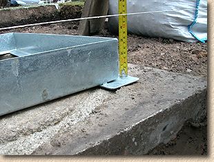
In this case, when the frame is placed in position and the gap between the top of the frame and the level line is measured, it is obviously more than the 15mm mentioned above, so some form of regulating masonry will need to be constructed. By measuring the gap, the precise size of the regulating can be calculated.
To calculate the amount of regulating masonry required, it is necessary to allow for the depth of the Cover itself, the mortar bedding, and for the fact that it is standard practice to set the frame of any manhole or access cover 3-6mm lower than FPL. So, in a situation where a single course of regulating masonry is required, we need to allow for 2 mortar beds @ 10-12mm, plus the 3-6mm frame allowance, giving a total of roughly 25-30mm. This figure is subtracted from the measured difference and this gives the thickness of masonry required.
Ideally, the masonry would be engineering brick, but this is not always possible because the gap is too little, so some slimmer form of masonry is required. Any hard, inert material can be used: pieces of flags or edging kerbs, pieces of roof tile, slate, stone or "Ironwork Shims" which are specially manufactured strips of an approved material, available in various thicknesses, that are used singly, or in combination to adjust the Cover Level of the ironwork in question. Timber of any description is not acceptable - it degrades over time and the cover will then collapse.
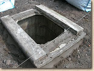
On our project, it is determined that we need to lift the level of the Tray and Frame by approximately 70mm, and this can be achieved by using salvaged pre-cast edging kerbs with mortar beds. The edging kerbs are 50mm thick, plus two beds of mortar at 10mm gives us the requisite 70mm.
Another batch of the Class II mortar is prepared, and a bed laid out on top of the Cover Slab.
The edging kerbs are laid out on top of the mortar bed and tapped down to level. The long edges are laid first, and then shorter pieces of the edging kerbs need to be cut to fit the short ends.
Once all the 'masonry' is in place and tapped down to level, the perpend joints can be filled with mortar and the internal face joint trimmed and cleaned as described earlier, again taking care to minimise the amount of mortar falling into the chamber.
III - Fitting the Frame and Tray
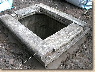
Once the regulating masonry is in place, the Frame should be temporarily placed on top and checked against the string line level guide, just to ensure that we're on target to achieve the required Cover Level.
Most Manhole and Access Covers will be laid to a fall that matches that of the pavement itself, and so, on a cover of this size (450x600mm) there may be 10-20mm cross fall from one side of the cover to the other. the string line level guide should be used to assess this, and it is important that the regulating masonry reflects this crossfall/endfall as accurately as possible. It is possible to generate some crossfall/endfall by using mortar beds of different thicknesses, but the scope is limited, as the minimum mortar bed is around 6mm, and, as mentioned earlier, the maximum should not exceed 15mm, giving a range of only 9mm. If necessary, the regulating masonry can be supplemented with thin shims of slate or similar material to provide the correct crossfall/endfall required of the cover.
The good news is that our project is bang on course to finish just 3mm below FPL, which is ideal, so, for now, the frame can be set aside, another batch of mortar prepared (yes, the same Class II 4:1 mix) and a bed laid out for the frame.
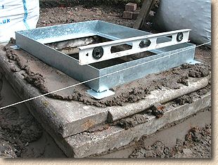
The frame is placed on the mortar bed and tapped down to the requisite level, using the string line as a guide, as well as the spirit level, if necessary.
At this point, it's also a good idea to check the alignment of the frame is 'square' or aligned to suit the pavement. If a square alignment is required, measuring the distance of each end of the frame from a wall or some other fixed line will indicate when it is properly aligned.
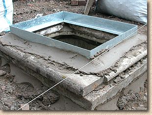
Once the level and alignment are correct, the frame can be haunched in place with additional mortar, which should cover the entire flange of the frame, but only extend up the side of the frame by 20-30mm, as sufficient room needs to be left to fit the paving or surfacing around the completed Tray and Frame.
The internal joints of the regulating masonry and the frame should be trimmed, tidied and pointed as usual, and then the external joints smoothed, although no great deal of neatness is required.
The entire construction may then be haunched with concrete, if it is thought necessary. For the vast majority of residential driveways, this will not be required, but it is often done when the regulating masonry has been constructed form materials other than 225mm wide Engineering Brickwork or when exceptional loads are anticipated.
Any haunching that is used should be kept lower than the level of the bedding layer or base course layer of the planned pavement. It should be compacted and polished with the back of a spade, and kept relatively neat. Bear in mind that, where a flexible sub-base is to be used, any concrete haunching could cause differential settlement , and so care should be taken to keep haunching to a minimum.
Finishing Off
The hard work is now complete, but, before dropping the tray into the frame, there's a bit of absolutely essential housekeeping to be done.
During the construction, it's inevitable that some debris and a few dollops of mortar will have fallen into the chamber. This MUST be removed - if left in place, it will cause problems with the drainage system, possibly even causing a blockage, either in the chamber itself or further along the system, if the debris should be washed someway downstream. Blockages are bad news - at best, it's a dirty, nasty, smelly job to clear them, but in many cases, it requires specialist tools and equipment and is often accompanied by a large bill.
So, clear out as much debris and mortar as possible. A child's beach bucket fastened to a length of rope can be dropped into the channel and a trowel lashed to a cane or a brush stele can then be used to push the contaminating matter into the bucket and hauled out to be disposed of elsewhere.
It's impossible to extract every last bit of rubbish and mortar in this way, but once as much as possible has been removed, the chamber can be flushed clean with a few buckets of water of a hose pipe. Take care not to wet the still plastic mortar, or you risk ruining all your hard work, but makes sure the channel is clean and clear, and that the benching is as clean as possible.
Finally, place the tray into the frame. This will prevent any further debris falling into the chamber, and keep it safe from children or the terminally curious.
The construction should be allowed a minimum of 24 hours for the mortars and concrete to harden. Where regulating masonry has been used, it's best to give it at least 48 hours, preferably 72 hours before putting a plate compactor or any other compacting equipment anywhere near the masonry. On jobs where speed is of the essence, using a haunching around the regulating masonry offers it additional protection and makes it possible to compact any fill or sub-base material 4-6 hours after construction is completed, providing extreme caution is used.
Before fitting the paving to the tray, check the chamber one more time, just to ensure no further debris or mortar has fallen in, and that the internal face of any regulating masonry is clean and tidy.