Introduction:
All paving and landscape projects need to be 'set out' - this is the process of using geometry to establish lines, levels, curves and arcs, as well as positioning other features in relation to a given point, typically a house, or other building.
On larger projects, automatic levels , theodolites, laser levels and even GPS are used to assist in the setting out, but there are some basic setting-out skills that require nothing more technical than a string line, an accurate spirit level, a tape measure, a handful of marker pegs, preferably 12mm steel road pins, and occasionally, a calculator, all of which should be readily available to most diy'ers.
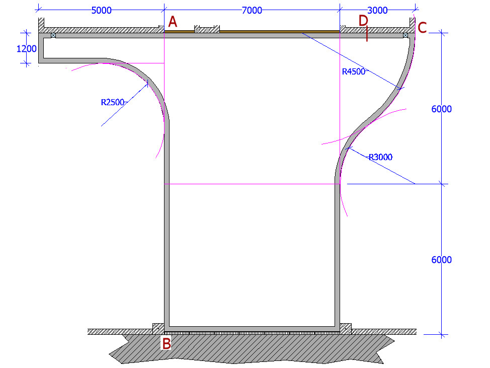
To illustrate some of these basic principles used in setting out, the plan for a typical driveway shown below will be used as a case study. This is a fairly common layout scenario for a block paved driveway.
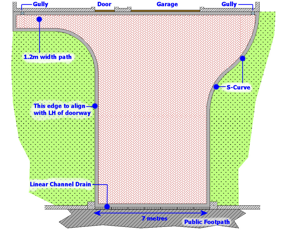
The brief is to create a drive 7 metres wide, which is to align with the left hand edge of the front door, with a curved sweep on the right hand side to accommodate the double width garage and a smaller curve on the left hand side to tie in with a 1.2m wide pathway along the front of the property.
The drainage of the pavement is catered for by existing surface water gullies collecting from downspouts located on both front corners of the property. The general level of the site is flat, with no more than 50mm of fall from the paving level at the front of the house to the threshold with the public footpath.
Fastening string lines
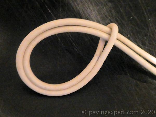
Much reference is made in these pages to the use of a taut string line as an aid to line and level. The string line is fastened onto steel marker pins using two standard 'knots'. In the photos, a length of thick white cable has been used to make the line more visible, but in practice, a nylon or fine cotton string about 2-3mm in diameter, is used.
The string line needs to start somewhere, and so a 'double loop' is used to fix one end of the line to the first pin. The double loop is twisted as shown in the picture opposite, and then placed over the starter pin, and adjusted to the required level. This is sometimes known as a 'Cow Hitch'.
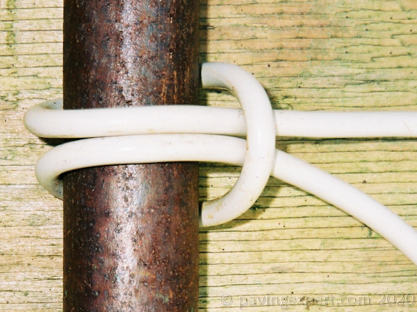
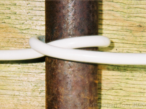
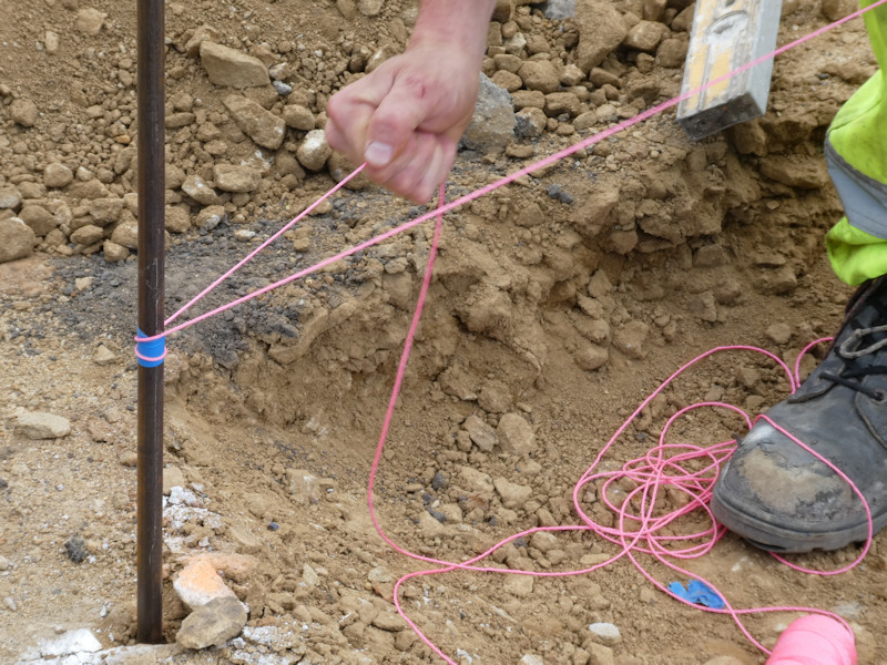
Once the string line is securely fastened onto the first pin, it is paid out to the next pin and fastened to that by means of a 'half hitch' or 'friction hitch', as shown in the photo opposite. A half hitch such as this depends on tension from the preceding length of line to hold itself in place, and so, in the picture, the line is feeding in from the left hand side, pulled tight and then brought around the pin and under itself, where the tension then holds the loop in place.
These half hitches are used on subsequent pins until the work in hand is completely set out. As has been mentioned, curves and arcs may need pins to carry the line at relatively short intervals; with straight sections the pins should be positioned no more than 10m apart, provided that the string line can be sufficiently tensioned to prevent any sag. If a line is sagging, it gives a wrong guide for level, and so it may be necessary to use pins at, say, 5m intervals.
Establishing Straight Lines
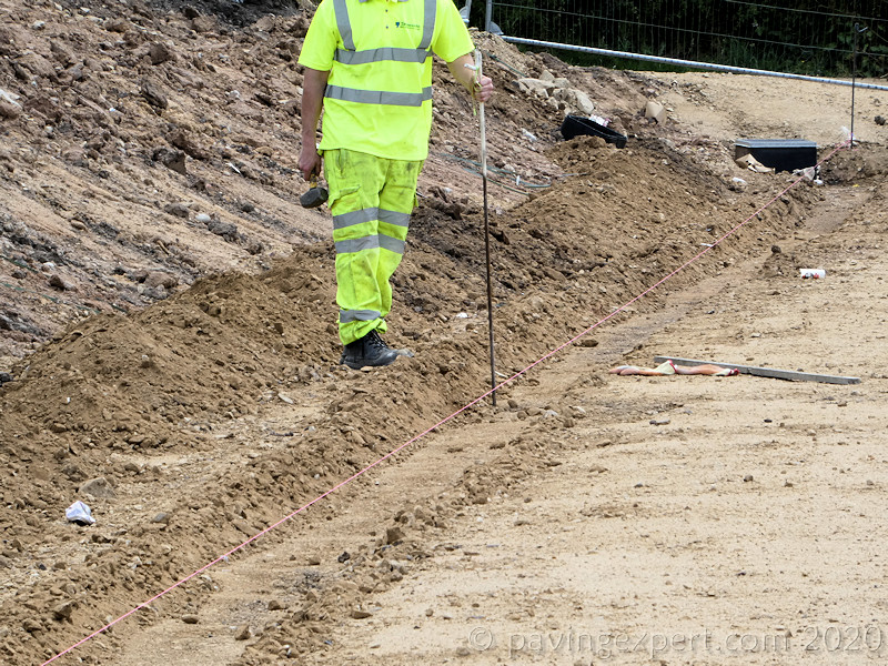
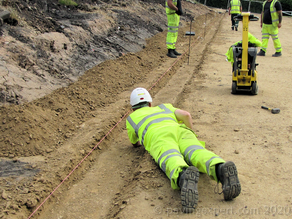
When setting out a straight line with intermediate pins, the start and end pins are positioned first, a string line pulled tight between the two, and then the intermediate pins established so that they are just touching the taut string line. If the pin is not touching the line, or if the line is deflected by the pin position, this will lead to a 'dog-leg', ie a kink, in the supposedly straight line.

On long straights, the intermediate pins are established by halving the distance between two existing pins. So, for example, on a 100 metre run, the start pin is established at 0 metres, and the end pin at 100 metres. The first intermediate pin is established at 50 metres, checked for accuracy and the string fastened to it, usually with a half-hitch. Next, two further intermediates would be established at 25 metres and 75 metres, and again, the string line is fastened to them once their position has been checked. This routine continues, with intermediates being established at 12.5 metres, 37.5m, 62.5m and 87.5m, and then possibly at 6m, 18m, 31m, 43m, 56m, 69m, 81m and 94m. Once all intermediates are in place, the alignment of the string line should be visually checked for accuracy by sighting along the line.

(Photographs produced with the generous and patient assistance of Tameside MBC Highways)
Setting out a perpendicular
A perpendicular is a line that is at exactly 90° to a base line. They are essential to accurate setting out, and are constructed using one of the fundamental principals of building work, the 3-4-5 triangle. From Pythagoras' theorem, we can establish that any triangle that has side lengths in the ratio of 3:4:5 must be a right angled triangle.
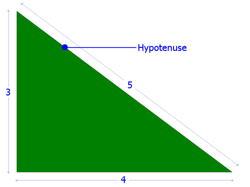
It doesn't matter if the side lengths are 3m, 4m and 5m, or 60 feet, 80 feet and 100 feet - as long as the 3:4:5 ratio is maintained, the triangle will have a right angle. With longer side lengths, however, accuracy of measurement can be become a problem, so we try to use a triangle with a maximum hypotenuse length of around 15 metres, although this is not always possible. With larger triangles, we will perform more check measurements to ensure accuracy.
Putting this knowledge to practical use, we can see from the construction plan for the driveway that the shape of the drive is constructed from a series of rectangles and arcs. The most important line to be set-out is the left-hand edge of the driveway, line A-B marked in red on the drawing, which is perpendicular to the front of the house, and is aligned with the left-hand edge of the doorway. To establish this perpendicular, we use a 3-4-5 triangle.
Here's a dimensioned version of the site layout plan....
The dimensions on the drawing states that the distance from the left hand edge of the front doorway (A), to the right hand corner of the property (C) is 7m + 3m = 10m. However, most landscape plans are drawn at a scale of 1:100 or greater, and will usually have an accuracy of around ±50mm.
For our right angled triangle we need to be as exact as possible with our measurements to ensure we get a true right angle at 90°, and not at 88° or 91°, so a measure is made along the front of the house, from the LH edge of the doorway at 'A' and a distance of 8m is marked with crayon or chalk at point D, just to the right of the garage door.
8m has been chosen as the length of the base line A-D because it is a multiple of 4, the largest side of the 3-4-5 triangle other than the hypotenuse. The base line is regarded as true (accurate - a genuinely straight line), and so the longest available edge, ie, the '4' always goes along the base line.
From these two fixed points, A and D, we now mark out two arcs. These can be scratches on the ground, sand lines, spray paint, crayon or anything that can make a mark. From Point A we mark out a 6m arc, ie, the '3' side of the 3-4-5 triangle, and from Point D we mark out a 10m arc, ie, the '5', the hypotenuse. Where these two arcs intersect, Point E, marks the apex of a 3-4-5 triangle.
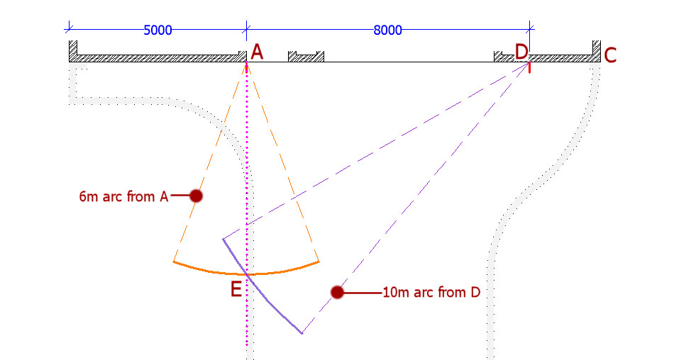
Using two tape measures, these can be used in place of arc marking, provided that you can anchor the tapes ends securely at points A and D. Pull the two tapes towards point E, and where the 6m mark on the tape from A meets the 10m mark on the tape from D, is exactly point E. Drive in a steel pin to mark the point.
If we now draw a line from point A to point E, we have a line that is perpendicular to the front of the property, and aligned as required with the left hand edge of the doorway. A stake or steel pin is knocked into the ground a point E. A string line is securely fastened to point A, and pulled tight, past the marker pin at E and extended all the way to the threshold of the drive. As long as the line is just touching the marker pin at E, the perpendicular line created from the 3-4-5 triangle is extrapolated and point B can be established and marked with a steel pin.
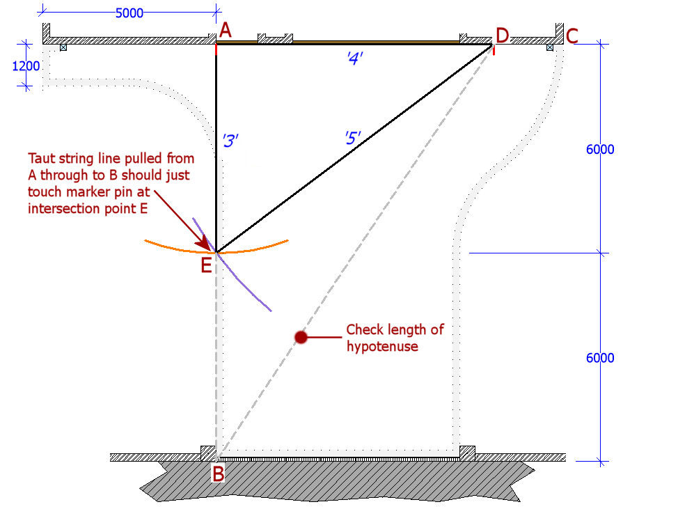
The accuracy of the perpendicular can be checked by measuring the hypotenuse B-D. We know that A-D = 8m, and we can measure that A-B = 12m. Pythagoras tells us that the hypotenuse, B-D is equal to the square root (√) of (A-D) ² + (A-B) ²
B-D = √(8² + 12²)
B-D = √(64+144) = √208 = 14.42 metres
The distance from point B to point D is measured and checked against the calculation for accuracy. In this example, a measurement of between 14.40m and 14.45m will be satisfactory as a check. If the measure is outside this tolerance, check the perpendicular again, setting out an alternative 3-4-5 triangle from the base line, if necessary.
Setting out arcs and curves
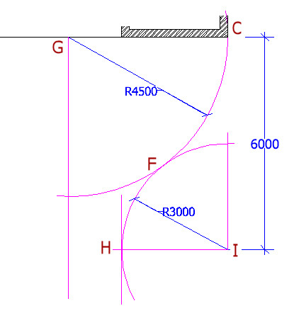
Arcs and curves are much simpler to set out. Any arc has 3 important points, namely the start tangent point , the end tangent point and the origin . A tangent point is the point where an arc just touches or intersects a straight line or other arc. In the drawing below, Points C, F, and H are all tangent points.
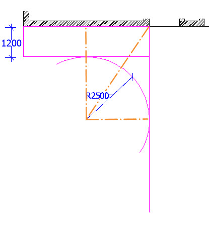
Referring back to our construction plan, we can see that two arcs are used on the right hand side of the driveway to make an 'S' curve. The 4.5m arc has its origin at G, and a tangent point with the building at C - so G must be 4.5m from C, the corner of the building.
The 3m arc has its origin at I, with a tangent point at H, where it meets the line that continues towards the public footpath. Where these two arcs 'kiss', at point F, is also a tangent point, common to both arcs.
It should be noted that these two arcs are very simple, in that they are orthogonal, ie, their origins and major tangent points coincide with other construction lines that are 'square' (ie: true perpendiculars or parallels) to the base line of the front of the house. In some situations, the origin of an arc might be inaccessible, for example, it could lie within the building itself, or be obscured by trees. In such cases, accurate setting out of arcs can be achieved by the use of chords (straight lines connecting two known points on an arc), or 'inverse arcs'. This is dealt with on the Setting Out Obstructed Arcs page.
To establish the 4.5m arc, a measurement is made along the face of the building, and the origin marked at 4.5m from C, ie at point G. The tape measure can now be anchored at point G, and used to scribe out the arc by swinging it around, from C towards H, marking in spray paint or similar.
Establishing the 3m arc is a little more tricky. We can see that its origin, I, is located on a perpendicular from the building, aligned with the corner, C, and is 6 metres from the base line. Perpendiculars can be constructed, as detailed above, to locate the exact position of its origin, I, the tape then anchored at I and the resulting arc scribed in the same manner as the 4.5m arc. If all goes according to plan, the two arcs will 'kiss' at point F - the common tangent point.
On the other side of the planned driveway, there's a simple 2.5m arc, and, as shown in the sketch above, if a rectangle is constructed (using the pronciples outlined above) and has the dimensions (1.2 + 2.5 =) 3.7m by 2.5m and aligned to the LH corner of the entrance doorway (which is also the LH boundary of the main driveway), the lower left corner of such a rectangle will be the origin point of the 2.5m arc required.
As a simple check for accuracy, the length of the hypotenuse (shown running top right to lower left inside the rectangle) can be calculated and measured on site to ensure that origin pin is in the correct postion.
3.7m² + 2.5m² = hypontenuse squared
13.69 + 6.25 = hypotenuse squared
19.94 = hypotenuse squared
√19.94 = 4.47m = hypotenuse
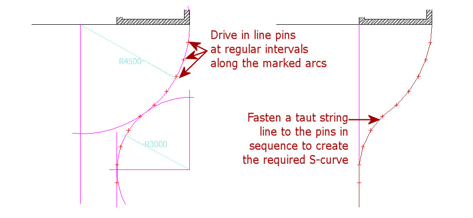
All that remains now, is to drive in marker pins at regular intervals along the arcs. The separation between marker pins will depend upon the radius of the arc. The larger the arc, the greater can be the separation between two marker pins. For these two arcs with radii of less than 5 metres, we would typically use marker pins at 600-900mm separation.
On the plan below, the marker pins have been positioned at 750mm centre to centre (c/c) along the arcs. Once in position, a taut string line can be fastened to the pins to create a line guide for the laying of the arcs.
Using the two basic methods outlined above, it is now possible to set out the whole driveway with marker pins and a taut string line. However, this only gives us a line guide, a guide to the shape of the driveway. Next, we have to establish levels, to ensure that the driveway is sloping (falling) in the right direction to drain away any surface water. The height of the taut string line above ground level is adjusted at the marker pins to give us a guide to both line and level.
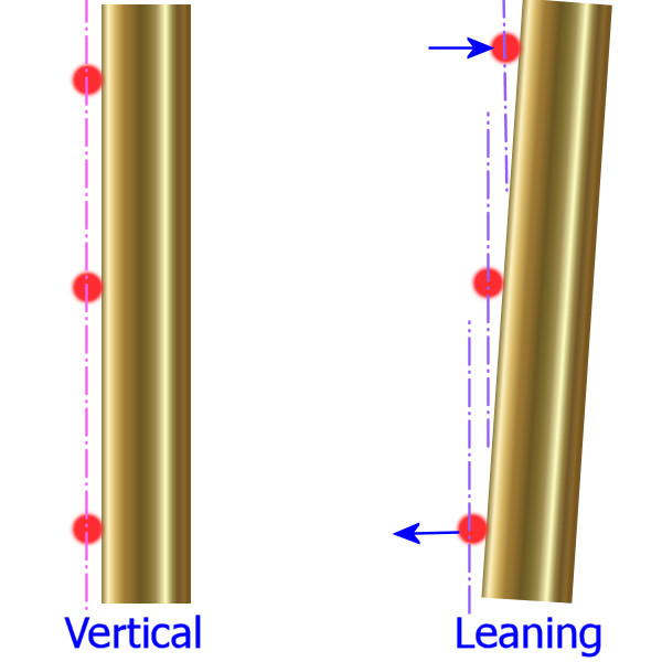
It is essential for accuracy that the pins are driven into the ground deep enough to be secure. They must be absolutely plumb, ie, vertical, otherwise, when the string line level is adjusted up or down the pin, the position is amended as well as the height, causing an error in the layout.
The diagram opposite is a cross-sectional view of the line, in red, and a pair of pins. When the pin is vertical (plumb), moving the line level up or down the pin makes no difference to position (side to side), whereas on the leaning pin on the right, adjusting the line level results in the line position being displaced to the right or the left.
It might only be a few millimetres, but when attempting to create a straight line or an accurate arc, that much of an error will be noticeable.