Other pages detail Fittings and connections made via access chambers, branch junctions and saddles.
Types of Connections
There are 4 ways to connect new drainage to an existing system:-
- - via a new branch junction or access chamber to an existing pipeline
- - via a saddle onto an existing sewer
- - via an existing manhole or existing inspection chamber
- - via a new inspection chamber or new manhole
On this page, methods 3 and 4 are the main focus; methods 1 and 2 are looked at on the Connections page.
Types of Chambers
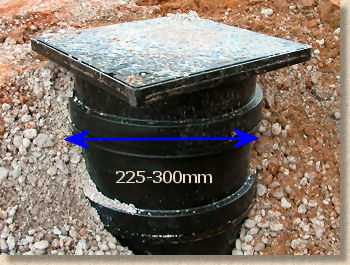
Access chambers (as discussed on the Connections page) are intended to provide simple access for cursory inspection and access for drain rods or other maintenance equipment. They are not intended to provide access for a maintenance operative and are generally not more than 600mm deep.
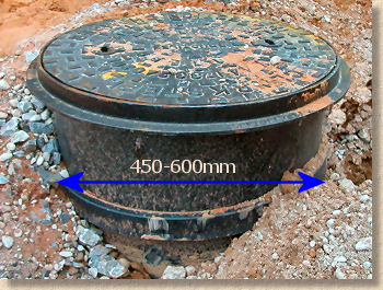
Inspection chambers (often abbreviated to IC) are larger than access chambers, typically a minimum 450mm diameter. Again, they provide access for maintenance equipment, but tend to have more branches/spurs feeding into them and are often up to 1000mm deep.
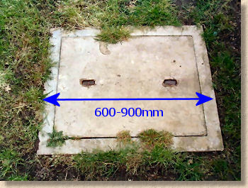
Manholes (MH) are the largest chambers providing access to a sewer or drain for maintenance equipment, and, in some cases, for operatives to enter the system itself. The minimum internal dimensions of a manhole are 600x900mm and they can be of any depth, although most modern manholes tend to be at least 1 metre deep with inspection chambers used for shallower depths.
Working Safely
Note: Manholes and sewers are exceptionally dangerous places. Noxious gases may be present that can injure and kill. It is most strongly recommended that all work on live sewers is undertaken by drainage specialists who have successfully completed a 'Confined Spaces' and/or 'Sewer Working' safety course rather than diy'ers. Properly trained and accredited tradesmen will have certificates to prove their competence. DO NOT TAKE RISKS.
Connecting to an existing IC
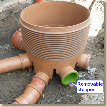
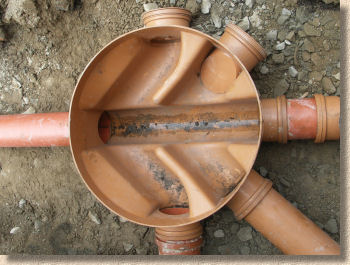
Most properties built since the 1980's will have circular inspection chambers at key points along the drainage system, such as changes in direction or junction. By removing the cover and checking the internal layout of these ICs, it is a simple task to ascertain whether there are 'spare' inlets available which can be utilised to form the required new connection. Any 'spare' inlets are usually stoppered from the outside with a plastic cap to prevent mud or debris from entering the chamber from the outside.
Any additional new drainage can be connected to the system via one of these inlets provided that the inlet is the same size or larger than the pipework to be connected. Excavating outside the chamber will expose the stopper cap, which is then removed and the new pipework connected in its place. In cases where the inlet is a larger diameter than the pipework being connected, the use of a taper pipe will allow the connection to be made.
Reflex Connection
One question which has been asked several times concerns connecting a new drainage point to an existing IC where the direction of flow from the new is opposite to that of the existing. There seems to be some sort of perception that connecting two pipelines that are effectively running in opposite directions will cause all sorts of problems.
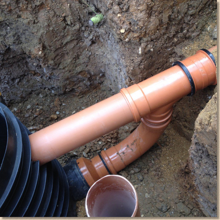
If the new line was brought in to the IC at 180° to the main direction of flow, this could, in certain arrangements, lead to problems, but what happens in practice is that we construct what we refer to as a Reflex Connection.
In essence, the line of approach of the new drainage is curved so that it comes into the chamber at an angle of 90° or less. As usual, this is explained most easily using diagrams...
The scenario is that a linear channel has been installed but the most direct route from the outfall of the end channel to the nearest IC runs counter to the direction of flow in the existing line of pipes.
The solution is to introduce a bend or curve into the line of pipes connecting the linear channel to the IC so that the new pipe enters the IC at an angle of 90° or less. By adding a curve to the line, we are reducing a reflex angle (an angle greater than 90°) to an acute angle (90° or less) and so 'easing' the inflow of collected water into the main channel and the pre-existing direction of flow.
The key feature is that the curve, created by using bends, MUST be located immediately adjacent to the IC.
In theory, there would be no great problem in setting the bends some distance from the IC. A rocker pipe of, say, 1m length could be connected to the IC and run out to the right before the bends necessary to create the required angle of turn are fitted, followed by a straight line of pipes direct to the linear channel outlet. However, this is not done in practice because once the whole lot is backfilled and long-forgotten, some future investigation of the drainage system would assume (quite reasonably) that the pipe line connecting the linear channel to the IC would take the most direct route and that by digging at a point 1.2m or so to the right of the IC there would be no chance of accidentally hitting a pipe.
Installing a new Inspection Chamber
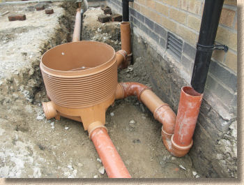
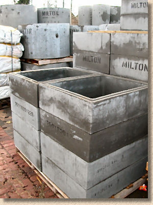
These polypropylene (PP) Inspection Chambers have a diameter of 450-550mm and cost around £80. Raising pieces are used to deal with deeper drains, up to a maximum of 1 metre; anything deeper than 1000mm requires a brick-built or concrete section manhole .
The 100mm types have 5 inlets and one outlet; unused inlets are stoppered to prevent ingress of spoil. The base unit should be laid on a 100mm thick bed of concrete and the raising pieces checked for plumb (verticality) before backfilling. If placed within a driveway or other trafficked area, they should be surrounded with 150mm of concrete all around to prevent deformation, and a heavy duty cover used. The chamber, or raising pieces, can easily be cut with a saw to accommodate the frame for the cover at the correct level.
The base unit should be connected to the drainage system by means of rocker pipes, that is, short lengths of pipe, 300-600mm in length that will allow some slight movement of the IC and/or the rest of the drainage system without imposing and stresses onto the joints.
Details of how these pre-formed inspection chambers can be inserted into an existing line of drainage using rocker pipes is given on the Connections page.
Connecting to an existing manhole
Although pre-formed plastic manholes (much like larger, stronger versions of the ICs illustrated above) are now becoming popular in the UK building trade, most existing manholes will be either brick-built or constructed from pre-cast concrete (PCC) sections. With both of these types, it will be necessary to break into the manhole to install a new connection.
Brick-built manholes typically have 215mm thick brickwork, which can be difficult to break through, unless a heavy-duty percussion drill is used. Alternatively, it may be possible to 'stitch-drill' the brickwork to make removal by hammer and chisel considerably easier.
PCC manhole sections are usually only 50-60mm thick, although those built beneath vehicular trafficked areas should have been haunched with mass concrete at least 150mm thick. It is best to 'stitch-drill' these sections to prevent fracture or spalling of individual sections. Use a 13mm masonry bit to drill holes to the circumference of a circle with a diameter of (external pipe dia + 25mm) at 25-35mm centres. The concrete can then be broken out with hammer and chisel with no danger of a catastrophic crack.
This idealised manhole is shown to illustrate how the channels and benching appear. Benching is the name given to the infill concrete between the channels and the brickwork. It is always raised and shaped to prevent sewage or rats lodging thereon.
Although the manhole depicted is brick-built, the same principles apply to pcc section manholes. Whenever brickwork is used to construct a manhole, whether it is beneath a vehicular area or just subjected to foot traffic, it should be double-skinned engineering bricks, 215mm wide.
This is our idealised manhole again, shown in plan view. The direction of flow is towards the bottom of the page, and a channel junction has been used to collect from the inlet pipe on the right.
A new connection is to be made on the left hand side of the chamber to collect from the soon to be installed pipework that will connect to a new gully or similar. A hole needs to be made through the brickwork to allow the pipe into the chamber.
There are two possible ways of installing the new branch to the manhole, depending on the type of system. On a surface water system, a 'stepped invert' connection is often permissible, but on foul or combined systems, a 'flush invert' connection is preferred. Both of these methods are outlined below.
Drop Shaft or Back Drop Connection
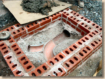
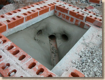
In some instances, there may be a significant level difference between the incoming pipe and the invert level of the manhole. To accommodate this, and to avoid having to excavate to full depth for the incoming pipe, a Dropshaft connection may be used.
The incoming pipe is projected through into the chamber, to enable rodding and cctv access, and then stoppered, as shown. A Tumbling Bay Junction is used to divert the flow downwards, through the vertically set backdrop pipe(s) and then via the knuckle bend to enter the chamber at invert level.
Surface water systems - stepped invert
In a surface water chamber, it sometimes acceptable (depending on Local Authority Inspectors) to project the pipe into the chamber in such a way that the bottom of the pipe rests upon the benching and the water is allowed to discharge over the benching and into the open channel.
It is essential that the new connection discharges its flow in the same direction as the flow of the existing pipeline, and not 'against the flow'.
Alternatively, the base of the branch channel is allowed to sit on the lip of the main channel, although the branch channel itself is cut to such an angle that it does not project into/over the main channel itself.
It may be possible to use a 'slipper' bend to form this type of stepped invert connection.
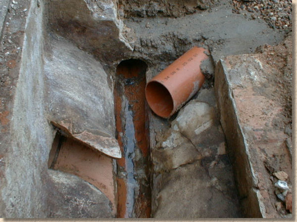
The pipe entering from the left is a slipper bend stepped invert
Once the branch channel or slipper bend has been positioned on top of the existing benching it should be secured in place with a granolithic or waterproof mortar , smoothed and shaped to eliminate any potential snags and sloped to avoid the formation of ledges. The pipe can then be fixed in place and the hole sealed with the same mortar or a concrete.
Note the maximum measurement (150mm) given for the length of pipe outside the manhole. This is known as a 'rocker' joint, and is intended to provide flexibility to accommodate any ground movement. As the manhole chamber is essentially a solid mass held together by concrete, the rocker joint ensures that small ground movements will not result in pipes being fractured or split. This applies to both plasticware and clayware.
Foul/Combined systems - flush invert
For a manhole on a Foul system, or a combined system, the above method is not recommended, primarily because it creates nooks and crannies where sewage may cling, and could, in some scenarios, cause a blockage to the chamber.
It should also be noted that the warnings given regarding surface water manholes are even more pertinent to foul systems, and it is strongly recommended that this work is done by competent and properly trained tradesmen.
To connect to such a manhole, the bottom of the incoming pipe, known as the 'invert level or IL', must be as close as practicable to the invert level of the existing channel. This can only be achieved by either breaking out the existing benching on the left-hand side of the idealised manhole to allow a new 'branch channel', sometimes called a 'slipper bend', to link the existing channel with the new pipe, or by breaking out a section of main channel and the benching to the left hand side and fitting an appropriate branch junction.
In this scenario, the new pipework is bedded down on a strong mortar (1:3) within the cut-out benching which then needs to be re-built. A granolithic mortar is normally used for this purpose, but any depth of re-building greater than 30mm should be first built up with a semi-dry strong concrete (1:2:4 or C20) and topped with a 30mm granolithic screed. The finished benching should be smoothed with a steel trowel and should have a fall of not less than 1:30 towards the channels. It is essential to ensure that there are no 'gaps' that would allow water to penetrate beneath the benching. There should be no 'snags' or lips on the benching that may impede the free flow of sewage.
Constructing a new manhole
Access and inspection chambers are used when the depth to the drain is a metre or less; for anything deeper, something more robust is required. The most common forms of manhole construction are...
- brick-built
- sectional pre-cast concrete
- sectional plastic
- cast in-situ concrete around a plastic liner
For depths up to 2.7m, the minimum internal dimensions for a rectangular manhole are 1200x750mm, although manholes with more than 3 branches may be even bigger. Anything deeper than 2.7m is a major project best left to professional drainage contractors.
Circular manholes are commonly used for main sewers; for depths up to 1.5m, they must have a minimum diameter of 1050mm, and for anything deeper than 1.5m, the diameter has to be 1200mm.
This x-section shows a typical construction for a manhole in a residential setting, such as beneath a driveway. It depicts the two most common constructions, using, on the left, pcc chamber sections, and on the right, Engineering brickwork.
The cover detail may be different for a manhole within a trafficked area, or if a recess tray cover for block paving was to be used.
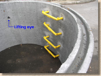
The step-irons should be built into the brickwork, or mortared into the pre-formed holes in pcc sections.
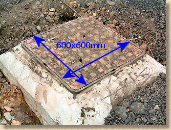
Note the minimum permissible opening size of any manhole is 600x600mm.
Plan view of typical manhole with a single branch oblique junction, again illustrating two construction types.
The number of branches entering a manhole will determine the length dimension. A manhole with more than 4 branches may need to be longer to fit them all in. Similarly, manholes utilising 150mm diameter channels may need to be larger.
Full details of manhole dimensions are given in BS8301:1985 Code of Practice for Building Drainage
If in doubt, consult Local Building Control Office.
Adoptable Manholes
Only properly trained and qualified construction professionals will be involved in the building of these types of manholes, and the construction requirements are more fully detailed in the invaluable groundworkers' bible , Sewers for Adoption 6th Edition 2006 published by the Water Research Council [ISBN: 1898920028] and generally accepted as the definitive guide to sewer work.
There are several different types of manhole described in SfA4, to suit a variety of purposes and conditions, but an idealised manhole construction is shown here to illustrate the basic concepts and components. Not all features depicted will be found on all manholes.
Some definitions:
- Shallow Manhole - a manhole that has a constant diameter or same cross-section throughout
- Deep Manhole - a manhole with an access shaft of a smaller diameter or plan size than the main shaft
- Cover and Frame - see table for guidance on strength rating of various covers
- Seating ring - sometimes used in place of regulating brickwork between cover and cover slab
- Brickwork - only engineering brick should be used, laid to English Bond
- Corbelling - the method of projecting brickwork outwards to reduce an opening or to carry a load. Each course should not oversail by more than 50mm
- Cover slab - also known as a 'biscuit'. Best thought of as a 'lid' for the main shaft, with a single access opening, minimum 600x600mm
- Reducing slab - used to accommodate a change in chamber diameter from a larger diameter main shaft to a narrower diameter entrance shaft
- Straight back tapers - perform the same function as reducing slabs, ie to accommodate a change in shaft diameter, but without providing a landing. Also known as 'Cone Sections'
- Landing Slab - used in Deep Manholes, these limit the maximum shaft depth to 6 metres, and may be thought of as shaft dividers, providing a resting point or 'landing' at convenient intervals
- Chamber sections - the individual sections used to construct a sectional shaft. Obviously not present with brick-built shafts
- Soffit - the underside of a cover slab, arch or other structure. Opposite of Invert
- Benching - a smoothed concrete topping, usually a granolithic mortar , sloping at not less than 1:30 and neatly shaped and finished to the base of a manhole
- Invert - the lowest point on the surface of a pipe, channel or culvert
- Rocker Pipe - a short length of pipe, usually less than 1 metre, placed at the inlet/outlet of a solid structure, such as a manhole or building, to accommodate differential settlement between the structure and the drainage system
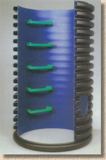
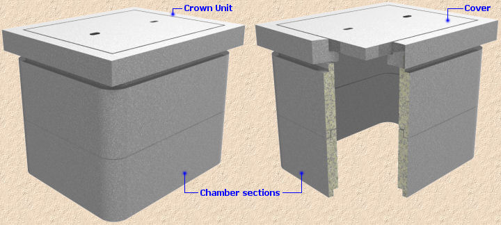
Cover Slabs
Cover slabs are the 'lid' for many manholes, especially the larger ones. They are also known as 'Reducing Slabs', because they reduce the opening size or the chamber dimensions, and, on site, they are affectionately referred to as 'biscuits' because that's the sort of humour that gets us sent to serve in the trenches.
The basic role of a cover slab is to provide a firm platform to both 'cap' the chamber and to carry the cover along with any regulating brickwork . They are typically manufactured in a high-strength, steel-reinforced concrete, and, for manholes, the minimum opening size of 600x600mm is created within the cover slab during the casting process. Although the vast majority of cover slabs are supplied fully-cured from specialist manufacturers, custom slabs may be cast on site and lifted into position once cured, or, in certain cases, cast in-situ atop the chamber itself.
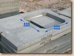
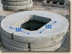
A secondary role for cover slabs is to reduce the apparent size of the chamber, so that, for example, a circular 1800mm diameter chamber or a rectangular 1200x750mm chamber, can be fitted with a standard 600x600mm cover at the surface.
These are heavy items, and they are generally fitted with two or more 'lifting eyes', which are steel loops embedded into the concrete, that should be used to sling the biscuits from a crane or excavator during lifting and placement.
The cover slab is normally mortar-bedded onto the top of the chamber with the internal face of the joint tooled smooth. When the surround concrete is placed around the chamber, it is brought up to be level with the top of the cover slab, as shown opposite. The regulating brickwork can then be built on top of the cover slab and the cover and frame fitted to suit the required level.

Manhole covers
Covers for manholes come in a wide variety of shapes, sizes and materials. The specification of manhole and access covers for public areas is laid down in BS EN124, which is summarised in the table opposite. Domestic driveways and patios often have the appallingly unattractive pre-cast concrete crown units and covers, and most block paved areas now feature recessed tray covers , fabricated from galvanised steel. Over recent years, covers manufactured from new high-strength composite materials have started to be used, primarily in pedestrian areas.
| Class | Test Load | Typical Uses |
| A15 | 1.5 | Pedestrian areas only |
| B125 | 12.5 | Car parks, domestic driveways,areas with occasional vehicle access |
| C250 | 25 | Carriageways if <500mm from kerb face, car parks, service stations.Must be non-rocking/silent type |
| D400 | 40 | Carriageways and hard shoulders.Must be non-rocking/silent type |
| E600 | 60 | Loading areas, docks,commercial/industrial areas |
| F900 | 90 | Exceptionally heavy loads, ports, airports |
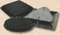
Table 1 - Cover Classification to BS EN124
Ductile and Cast Iron covers are manufactured to conform to BS EN124 but other materials, such as galvanised steel or pre-cast concrete are not included within the scope of that standard. Manufacturers of galvanised steel covers have formed a Trade Association (FACTA) in order to impose some standards and quality into the market, but, at the time of writing, there is no nationally or internationally recognised standard.
Most covers actually consist of 2 components; the cover itself, and a frame. The frame is typically bedded on mortar to a specified height set to suit the surrounding paving or ground level and the cover sits inside the frame, from where it can be lifted and possibly removed when access to the manhole is required.
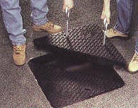
Many of the heavier units have the cover itself split into 2 triangles, known as 'double triangular' format. The two halves can be bolted together but are often left unattached to facilitate easier removal. Removal is achieved by the use of 'keys' which fit into the eyes on the surface of the cover, are turned through 90° and then it's down to brute force, although there are special cover-lifting contraptions now available.
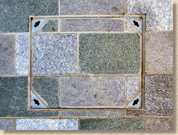
As mentioned above, many paving projects now use Recess Tray Covers rather than the types of covers illustrated above. Recess Trays can be used with any type of paving, although they are most commonly associated with Block Paving.
The uses, applications and fitting methods for Recess Tray Covers are considered on other pages of this website. Click here to access the Introduction to Recess Trays page.
SUDS Pages