Introduction:
Other, less obvious examples include fuel station forecourts, where there is a requirement to prevent any spillage penetrating and contaminating the sub-strata, and refurbishment of existing surfaces, especially existing concrete residential driveways.
The two most common materials used as a base course beneath flexible block paving are known in the trade as HBM (was CBM) and DBM - Hydraulically Bound Material (was "Cement Bound Material" - concrete to me and thee) or dense base course bituminous macadam (Bitmac/Tarmacadam/Asphalt). These are discussed in more detail on the Block Paved Highways page.
There are two major considerations that must be taken into account before constructing a flexible block pavement over an impermeable Base Course:
- Possible saturation of the bedding layer
- Compatibility of paving levels
Saturation:
As can be seen from the Block Paved Highways page, some projects rely on a Base Course, or Road Base as some call it, to give the pavement sufficient strength to carry the traffic. Quite often, the design for such a pavement will include some method of draining the bedding layer to prevent saturation of the bedding medium which can result in it becoming fluid which in turn leads to pumping and/or rutting and/or settlement. This is particularly true of unsealed block pavements; although a run-off value of around 95-98% can be expected from a mature block pavement, there will be some ingress of surface water, and, in certain situations, this can lead to saturation of the bedding layer.
Although a coarse grit sand or grit is less liable to fluidisation than a soft building sand (hence its use for bedding pavings), hydrostatic pressure resulting from the build-up of water between the pavers and the impermeable base course can cause problems. However, these problems can usually be overcome by inclusion of some form of bedding layer drainage.
Drainage Techniques
There are several possible strategies that can be employed to drain a bedding layer and reduce or eliminate the risk of saturation. All of them are extensions of principles outlined in the Drainage section of this site, and so, only the basics will be explored on this page.
There are two popular techniques used to drain the bedding layer of projects such as low-speed highways, commercial pavements and civic areas. These are Edge Drains, which evolved as an adaptation of the perforated pipe technology examined on the Land Drainage page, and Horizontal Drainage Composites, which are covered on the Fin Drains page.
Edge Drains
Originally, this technique worked by collecting any water that found its way into the bedding layer via a perforated pipe laid in a channel at the edges of the pavement. The perforated pipe eventually discharged to an outfall or the surface water system, thereby removing the water from the pavement completely.
In most cases, a fairly rigid uPVC perforated pipe was used, rather than the flexible corrugated pipe normally used for land drainage, as it had to be capable of carrying the pavement above without collapsing or deforming, which would have then led to severe, potentially dangerous, settlement of the pavement.
This is shown on the left-hand edge of the drawing below.
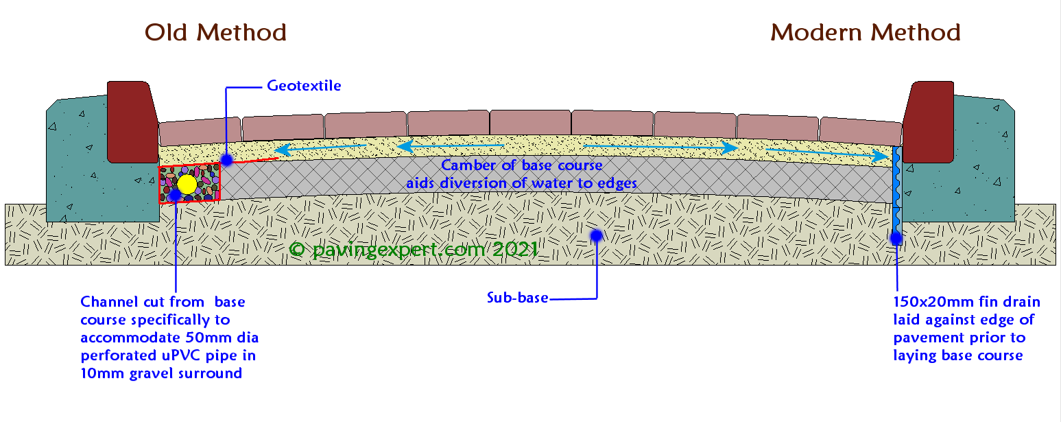
However, recent advances in the development of high strength drainage composites has seen the evolution of a vertical drainage composite, laid against the restraining edge of the pavement. Some systems use a typical fin drain while others rely on a shallow version of a fin drain, specifically designed to drain the upper layers of a pavement. These shallow fin drains, shown on the right-hand side of the drawing above, offer a significant cost saving, in terms of both materials and labour, and we expect them to become the standard method of draining this type of pavement in the coming years.
Horizontal Drainage Composites
This method of draining the bedding layer tends to be used beneath pavements that are expected to experience regular inundation for whatever reason. Unlike the vertical fin drains described above, horizontal drainage composites are in direct contact with the entire base course and so offer the possibility of faster drainage of any excess water.
The composite may drain to a standard fin drain laid beneath the pavement, as shown on the right hand side below, or may be connected to a collector pipe outside the pavement, as shown on the left hand side. Obviously, this type of installation requires a greater quantity of drainage composite than the vertical edge drain, and is consequently that much more expensive.
For a fuller understanding fin drains and drainage composites, how they are constructed and how they work, please refer to the Fin Drain page. As with other forms of drainage, these fin drains and drainage composites MUST have a point of outfall, whether it be a natural watercourse such as a ditch or river, or the surface water sewer. Some systems will outfall to a holding or settlement tank before discharging elsewhere.
Containment
In the case of Filling Stations, or other paved areas where there is a significant risk of chemical spillage, the use of an impermeable Base Course with a horizontal drainage composite will help minimise contamination, and direct any potentially harmful liquids to a holding tank or other disposal point for collection and treatment. For such containment projects, the drainage composite chosen would have an impermeable face laid in contact with the base couse and the edging units, while the permeable face would be in contact with the bedding layer, thereby allowing collection of any spilled liquids.
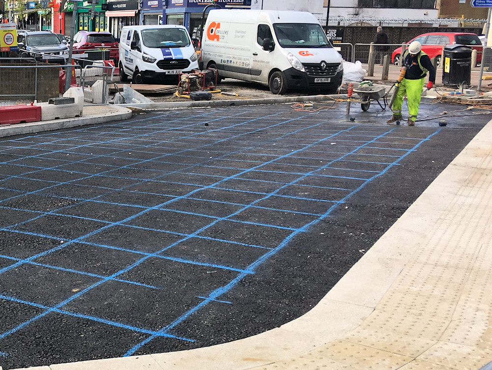
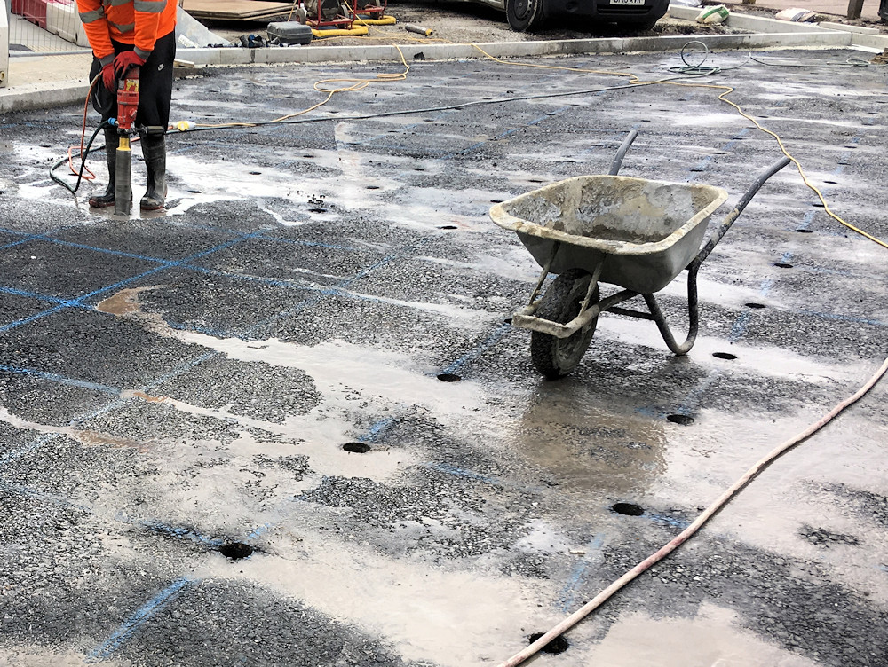
Vertical cores
Finally, here's a method that we have used on residential driveways where an existing base course was lying on top of an exceptionally well-draining sub-grade or sub-base. By core drilling 50-75mm diameter holes at regular centres through the base course, and 'escape route' is created for any water that finds itself trapped between the blocks and the otherwise impermeable base course. It should be noted that we have NEVER used this method on a commercial project, and cannot vouch for it efficacy on all jobs, but, on the few occasions when we have used it on residential driveways, it has worked well.
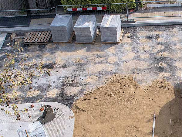
The holes are typically drilled at 1-to-2 metre centres, and once the core is removed, they are filled with a clean gravel which is compacted down with a punnel. The entire base course is then covered with a separation membrane, usually Terram 1000, to prevent the bedding sand being washed through and lost. The block-laying work then proceeds as per usual.
Overlay of existing Surfacing:
Given the high cost of breaking out and disposing of an existing surface, there are some situations where an overlay of block paving is considered more cost-effective. There are some limitations on the use of this solution, the most notable of which is the problem of tie-ing in with existing damp proof courses and thresholds.
Any block overlay is going to elevate an existing surface by at least 85mm, often more. However, any solid pavement is required to be kept at least 150mm below the level of a damp proof course on a building, and so, for an overlay to be used successfully, the original surface must be at least (150+85)= 235mm below dpc. Where thicker blocks need to be used (bearing in mind that 50mm blocks are only suitable for light domestic use) the minimum distance between original surface and dpc will need to be 100mm (60mm block + 40mm bed) or even 130mm (80mm block + 50mm bed).
Step and Channel
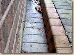
One simple solution to those situations where there is not sufficient distance between original surface and dpc to maintain the 150mm differential is the step and channel arrangement, illustrated opposite. This form of construction is sometimes referred to as a 'Dry Area Construction' and is considered in more detail on the All About DPCs page. In the example shown here, a kerb unit is used to contain the paving away from the wall with the dpc. Typically, the gap between the wall and the restraining kerb will be 200mm minimum. In some situations, the kerb may need to be cut down on its bottom face to allow it to be bedded on a Class II mortar over the existing surface.
Although a small-unit kerb kerb presents the tidiest solution to the problem of restraining and containing the pavement, a soldier edge of mortar-bedded pavers could be used, if preferred. Other possible restraints include an edging kerb, either decorative or flat-top, or even mortar-bedded setts/cubes. A timber restraint is not recommended, as it is likely to move.
In the example opposite the edge of the original concrete surface adjacent to the building has been broken out and removed, to be replaced by a deep kerb and a 200mm wide block that slopes away from the wall. There is a sufficient degree of endfall within the channel to ensure any water finding its way in there will run towards a nearby gully.
It is essential that the kerb, or whatever unit is used to restrain the pavement, is securely fixed to the base. Should this restraint fail, the pavement will fail. An adequate key is required on the free edge nearest the wall to prevent the kerb being 'pushed' out of place by the weight of the pavement and the traffic. For this reason, we prefer to bed the kerb in a chiselled-out trench as shown opposite.
Transition Ramp
Another issue with any overlay of paving is that it has to tie-in with the level of adjacent pavements, such as garage floors and public highways. Although this problem may be overcome by the use of transition ramps, in some cases, this would just not be viable.
Transition ramps require that part of the existing base be broken out and removed and then a sinusoidal (S-shaped) cross-section is created to reduce the level of the overlay pavement so that it ties-in with the fixed pavement/floor level. In the example illustrated below, a linear drain has been incorporated at the threshold to a garage, to prevent any ingress of surface water from the block pavement.
Note also how the sub-base material has to be shaped to maintain a constant depth of bedding sand. The boundary between the rigid base and the flexible sub-base can result in differential settlement over a period of time, therefore, it is essential that the sub-base material is compacted thoroughly. Alternatively, the sub-base material could be replaced with a bound material, such as concrete or bitmac, to reduce the risk of differential settlement.
Normally, a transition ramp would be at least 1 metre in length for each 50mm of height adjustment to be accommodated. However, in the example above, with an height differential of 100mm (60mm block +40mm bed), the ramp has been made just over 1200mm in length. This is quite steep, but has been done purely to illustrate the technique. On a real pavement, this transition ramp would be at least 2 metres in length.