The previous page considered the components and the prep work, and the last page will look at the finishing touches, such as the end caps and gratings.
Installation of Channel
The Aco Drive Drain should be laid onto a full concrete bed. This is especially important when used in a position such as this, where it will be repeatedly trafficked by vehicles which can nudge the channel out of line or cause settlement, but even when Aco Drive Drain is laid at the edge of a pavement or tight up against a wall, where it's unlikely to be trafficked, it' best laid on a bed of concrete or mortar.
However, it's worth mentioning that DriveDrain is a "Type I" channel at Load Class A, meaning it requires no bedding to reach its design load capacity, so, in theory, it can be laid directly onto any bedding material and does not need the added strength of, say, a concrete bed to ensure the channel achieves its intended strength rating.
As this channel will be trafficked daily by the car that is parked in the garage, it will be bedded onto 100mm of a reasonably strong concrete - a C20 mix (1:2:4) - and haunched with the same. For projects where the Aco Drive Drain will be trafficked by vehicles fairly regularly, a bed of 100m depth should be used.
A 150mm bed may be used in exceptional circumstances, but where site conditions dictate that a 150mm bed may be needed, it's likely that one of the Aco channels with a higher Loading Class will also be required. A 50mm bed is suitable only for installations where the Channel will not be trafficked by vehicles at all. This is summarised in the cross-section drawing above.
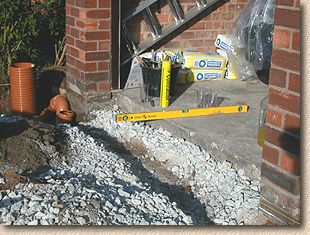
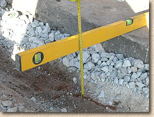
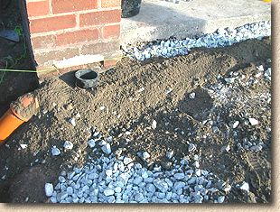
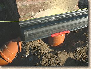
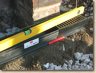
A taut string line is set up across the face of the garage. This will act as both a guide to level of the channel, and to its alignment between the two pillars. The line is established at a level that is approximately 12mm below the garage floor, as shown opposite.
This is done to ensure that there is no risk of surface water from the driveway washing into the garage itself, and so that, if any water was to be spilled within the garage, it can be swept out and into the Aco Drive Drain .
Excavation
We know from earlier that the channel itself is roughly 90mm in depth, and a further 100mm is needed for the concrete bed, so a trench with a depth of not less than 100+90=190mm below surface level has to be excavated to accommodate the channel and its concrete bed.
Bedding
For this simple project, the bedding concrete will be mixed on site with the aid of a powered mixer. For larger installations, concrete may be bought in as Ready Mix , but as this project will be installing only 4 linear metres of Aco Drive Drain , it is more economic to mix on site.
At 100mm depth of bed, each linear metre of channel will require approximately 0.034m³ of bedding and haunching concrete. The table opposite gives some estimates of the volumes of concrete required for various installations of Aco Drive Drain .
For 4 linear metres of Aco Drive Drain , plus some extra for haunching around the underground drainage, it's estimated that approximately 0.2m³ of concrete will be required.
Click here for a calculator that estimates the quantities of each ingredient required to mix a C20-equivalent concrete.
The concrete is mixed and placed into the excavated trench, and around the P-trap and other underground drainage as required.
Notice how a temporary 'cap' (actually one of the inlet caps from the Access Chamber fitted previously) has been placed over the P-trap. This is to ensure none of the concrete bedding material accidentally falls into the P-trap unit. Although it would be relatively easy to clean out any concrete from the trap before the channel itself is fitted, prevention is always better than cure.
The bedding concrete is a semi-dry mix, that is, it has very little added water, just sufficient to bind together the dry ingredients and initiate curing of the cement. We find that it is easier to bed linear channel, kerbs, and edgings onto a semi-dry bed than onto a concrete that is wet or sloppy.
At a depth of 100mm, simply tapping the channel down to level on the bed would not properly consolidate the full depth of the concrete, so, once the bedding is in place, it is trampled down and then the top 25mm or so is loosened and levelled out to accommodate the channel itself. Consequently, when the channel is tapped down to the required level, it need only consolidate the loose material and not the full depth of concrete.
Connecting-up
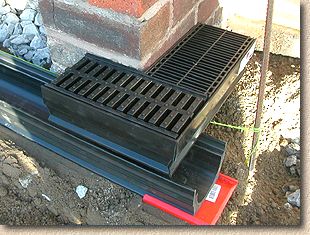
The first section of channel to be fitted will be the unit that will connect to the underground drainage.
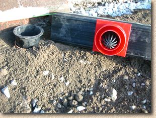
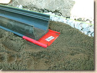
The Vertical Outlet unit is slid onto a channel unit and roughly positioned to match the positioning of the P-trap.
Note the Leaf Guard unit within the Vertical Outlet unit in the photo opposite. This can be removed for now, as we are only concerned with positioning, not with final fitting.
Note also the loose 'cap' protecting the P-trap, as described above.
A coupling is then fitted to the Vertical Outlet unit. This is simply slid into place, just the same as fitting a coupling to a length of pipe. A drop or two of wash-up liquid or pipe-laying lubricant applied to the 'male' end of the Vertical Outlet unit makes sliding on the coupling much easier.
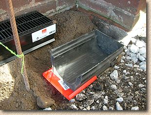
The concrete bedding around the P-trap is scraped back to expose the opening, the temporary cap is removed, and a raising piece is fitted. This raising piece is cut from a length of pipe, lubricated, and pushed into the 'female' receptor on top of the P-trap itself.
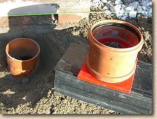
The concrete bed itself is prepared, the channel is offered into position with the coupling sitting squarely on top of the raising piece, and then gently forced down, driving the raising piece into the coupling and completing the union.
Ideally, the top of the channel will now be at the correct level, tallying with the taut string line established previously, but this is an imperfect world, so it's likely that some minor adjustment will be required. The channel should be tapped down using a small rubber mallet, or it can be 'packed' by forcing additional concrete beneath it from both sides.
Adding Further Sections
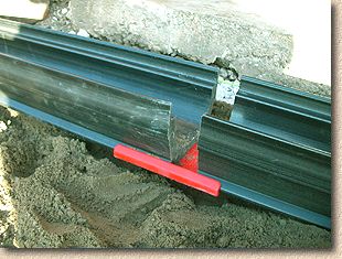
Now that the first section of channel is in place, other sections can be added quite simply. The concrete bed is prepared as described earlier, and a Connection Piece is slid onto the channel that is already in place.
We found that there was a tendency for bits of concrete and other detritus to fall onto the Connection Piece, and so before offering up the next section and sliding it into place, the Connection Piece was brushed out with a small hand-brush. This ensured no matter was trapped between adjacent sections and that a tight joint could be formed.
Once the Connection Piece is clean, the end of the new channel section is fed in, and pushed home until it abuts the previous channel section. It is tapped down to level using the rubber mallet, and checked for alignment with the taut string line.
There may be a small void beneath the Connection Piece, where concrete bed has been scooped out to facilitate movement of the Connection Piece. This should be packed full with additional concrete to ensure the channel section is fully supported along its entire length.
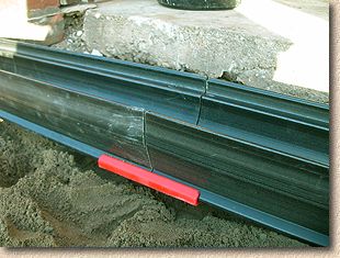
The process continues until all the required sections are in place - it really is that simple!
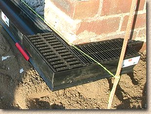
We found that the Channels were easy to tap down to level with or without the grating in place. We chose to remove the grating during this part of the fitting procedure so that we could clean out any debris or concrete as work proceeded. The channels are easy to tap down and simple to align.
Fitting a Corner Unit
At this stage, the channel laying is basically complete. The End Caps could be fitted, and the channels haunched to ensure they remain aligned until the paving is in place. However, on this project, we need to extend the Aco Drive Drain around a 90° corner.
With some linear channel systems, this may require a mitre joint to be formed, which is complex and time-consuming. Aco Drive Drain system includes a factory-prepared Corner unit that is more or less as simple to fit as a standard channel.
The previous line of channel sections have been laid and extended to the nearest full section beyond the corner. The Corner Unit can now be placed in position and used to mark the preceding channel where it will need to be cut to accommodate the Corner Unit.
The channel can be marked with a pencil or a sharp marking point, and then cut down using a cut-off saw, an angle grinder or even a standard "all-purpose" hand-saw.
Once the preceding channel section has been sawn down to the required length, the Connection Piece is put into position and the Corner Unit joined onto the line in the same manner as a standard section - just slide it into the cleaned-out Connection Piece and tap it down to level.
If you're wondering why the grating on the right-hand end of the Corner Unit looks so different to that on the left, it's because we temporarily put it in upside down. When we come to fit all the gratings, it will be corrected.
The level of the Corner Unit should be checked for fall in both directions.
Although fall is not always essential for such relatively short runs of linear channels, it is critical that the short run of channel now being fitted does not backfall: it must have some fall towards the main line of the channel, otherwise water will simply sit in the channel instead of draining towards the outlet.
For such relatively smooth drainage fittings, a fall of 1:100 is adequate.
The next task is to fit a short end piece to the Corner Unit.
The length of channel required is measured and cut, as before. As the 'end' of this short piece will abut the wall of the property, the End Cap is fitted to the short section before placing the channel itself, as it would not be possible to fit it once the channel is in its final position.
A Connection Piece is fitted and cleaned, and then the short section, complete with End Cap, can be joined on to the Corner Unit.