Principles
Soakaways are one type of "Infiltration Device", a simple way of dispersing surface and storm water in situations where connection to the SW system is impractical or unwarranted. The basic principle is that of a 'reverse well' i.e. a 'hole-in-the-gound' that loses water rather than collecting water.
Soakaways are one of the key technologies for SUDS - Sustainable Urban Drainage Systems. They enable storm water to be dealt with "at source" rather than being diverted into our over-burdened sewer systems. Find out more about SUDS on the SUDS Introduction page.
It should be noted that soakaways rarely work on heavy clay soils. If you are hoping to create a soakaway to alleviate waterlogging in a garden, you may well be disappointed by what follows.
The two determining factors for soakaway success are the size of the area (or volume of water) to be drained and the percolation rate of the soil/sub-soil (or, in some sites, the depth to the water table).
One of the first things to consider when choosing a site for a soakaway is the water table (aka saturation line). This is defined as upper level of the groundwater that is naturally held within the soil, sub-soil or bedrock. It is not uncommon for the water table to rise during the wet months of winter and to fall during the allegedly drier summer months.
In waterlogged sites, it is often found that the water table is exceptionally high (ie, near the surface). In cases such as this, a soakaway is just not going to work: think about it - to where will all the additional water you're planning to send to the soakway drain? There is nowhere for it to go. The 'soakaway' in this situation is not a soakaway at all; it's a hole full of water, otherwise known as a sump.
However, there are some sites where the water table is high, because there is a layer of impermeable clay overlying a deeper strata that might be porous. In such cases, digging through the clay cap and into the porous sub-strata will render a soakaway feasible, assuming that the depth to the porous strata is not prohibitive.
Site Requirements
Other than having a suitable geology, the site of a soakaway must also.......
- be in a spot lower than the area being drained
- be at least 5 metres away from any building (BS 8301)
- be sited so that it will not saturate the foundations of any structure
- be sited so that the base of the soakaway/infiltration device is permanently above the water table
- be sited far enough away from other Infiltration Devices to ensure the capacity of those devices, and the ground itself, is not impaired
- be sited so that there is no risk of contamination from pollutants
Site Investigation
Permeable sub-soils such as sands, sandy loams and the like, along with permeable bedrock types, such as limestone, sandstone or chalk, are usually good news for soakaways, whereas hard, igneous rocks, such as granites and basalts, and heavy, claggy soils may mean a soakaway is not going to be feasible.
A trial pit is used to determine whether there is a sufficient rate of percolation, ( Vp ) or depth to water table for the soakaway to function properly. A trial pit is, basically, a hole. BS 6297 gives the full procedure for determining the percolation rate by creating a hole 300mm square in plan and at least 250mm deep, and then measuring the length of time taken for water to percolate out of the hole. However, this is not always feasible or necessary. A simpler approach is to excavate the trial pit to establish whether a soakaway is likely to work or not, rather than determine just how effectively it will actually work.
For this, dig a hole at least 1.2 metres deep. Remember, any excavation deeper than 1.2m MUST be supported to eliminate risk of bank collapse. For small soakaways serving a single property, it is unlikely that a trial pit will need to be any deeper than 1.8m, and so it could be excavated as shown in the diagram opposite. For larger projects, where a trial pit up to 6 metres deep may be required, trench shoring must be used.
Leave the excavated trial hole overnight, covering with a board or fencing-off to prevent accidents. 24 hours later, inspect the pit. If there is no water in the trial pit, then a soakaway is highly likely to work and work well. If there is any water present, the level will have stabilised at water table level, and this should be measured from ground level and used in the following calculations to determine whether a soakaway is possible or practical.
How Big a Soakaway???
Assuming the trial pit has proved suitable, the next task is to calculate the size of soakaway that will be required. There are a few formulae used to calculate the required storage capacity for a soakaway, but the one we normally use is...
Vol = A × (rainfall rate/3000)
This formula states that the volume of soakaway required is equal to the area to be drained (in m²) multiplied by the product of the storm rainfall rate (assumed to be 50mm/hr in UK) divided by 3000. For example:-
Area to be drained = 60m², hence, Volume required = 60 × (50/3000) = 1m³
Note that this is the storage volume required between the dry base or water table level of the soakaway, and the invert (inlet) level of the incoming drainage pipe, and assumes that the chamber is empty, not filled with old bricks, lumps of concrete or gravel, etc., as is often found in older soakaways. If the chamber were to be filled with, say, a gravel, this would significantly reduce the storage volume, requiring a much bigger chamber to be constructed.
In the above example, if a 1000 × 675mm inspection chamber section (as shown in diagram below) is to be used, then the soakaway depth is calculated as...
1m³/(1 × 0.675)m² = 1.48m deep
If the invert level of the incoming pipe is, say, 600mm below ground level, and assuming the base is above water table level, then the overall depth of the soakaway is...
1.48m + 0.6m = 2.08m overall depth.
If there is insufficient depth because of a high water table, the required volume of the soakaway can be met by increasing the plan size or placing two or more soakaways of this size side by side.
For public or bigger commercial/industrial projects, large diameter segmental soakaways, such as the 6 metre dia unit manufactured by Marshalls shown opposite, can be used, although their installation needs heavy lifting equipment, ground shoring and the expertise of a professional drainage contractor.
Refer to BS EN 752:2008 for further information on surface water drainage and soakaways. Many manufacturers can supply purpose made soakaway sections and cover units - consult your local builders marchant for more detail of sizes, availablity and prices.
Construction details
There are a number of options to choose from when constructing a soakaway. Many older soakaways are little more than a hole in the ground filled with old bricks, clinker or gravel, but, as stated above, such a structure has a severely reduced storage capacity and modern soakaways are, usually, empty chambers of one form or another.
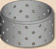
Ready-made systems, such as those shown here, are available from Builders' or Civils Merchants in pre-cast concrete or plastic. These tend to be circular sections that can be 'stacked' to give the required depth and storage volume, and then topped with a suitable cover.
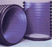
They are often laid on a simple ring foundation, a strip footing of concrete that supports the weight of the chamber section, although this may be omitted on hard ground or bedrock. A cover is essential to allow ingress for cleaning and inspection, and should be laid on 2-4 courses of regulating brickwork . In deeper chambers, step-irons may also be required. There should be at least 150mm of 10-75mm granular material used to backfill around the soakaway, and units having larger diameter weepholes are usually shrouded with a geo-membrane to prevent the backfill material falling into the chamber.
Pre-fabricated cellular systems:
A relatively new development (as part of the push for Sustainable Urban Drainage Systems [SUDS]) are these modular storage/soakaway cells. They are usually manufactured from recycled polypropylene and give incredible strength for very little weight. Also, with them being modular, many units can be linked together, in 3 planes, to give whatever capacity is required.
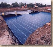
The units can be used as a standard soakaway or, if wrapped with an impermeable geo-membrane, they can be linked together, as shown opposite, and used as an underground storage system for stormwater.
We believe these systems will be used more and more in the construction industry as SUDS technology becomes mandatory rather than optional in the coming years, and they are a classic case of being one of those bright ideas that are blindingly obvious once you've seen them.
A guide to the installation of these modular cells for a residential project can be found in the SUDS section of this website
Small domestic solution
If you are using pre-fabricated soakaway sections, you should follow the manufacturer's specific instructions for installation, which may vary slightly from those given above. For small, domestic soakaways, the following method can be used or adapted to suit the site requirements.
The soakaway is constructed from rectangular inspection chamber sections, readily and cheaply available at most builders' merchants. The individual sections are separated from each other by using a brick or concrete spacer as shown. The inlet pipe is inserted into the chamber - perforated plastic pipe can be squashed to fit between the the sections, but larger diameter rigid pipes may require a hole to be cut in the concrete chamber sections with a power saw.
Before backfilling, the outside of the soakaway should be wrapped with a permeable geo-membrane to prevent fine particles and silts being carried into the chamber, leading to blockages and 'silting-up'. The exterior of the soakaway can then be backfilled with granular material, leaving the inside empty, before placing the cover.
Maintenance
A soakaway shouldn't require any maintenance, but it is a good idea to lift the cover and check the structure every few months or so to check for silting or contamination. If significant silting-up is occuring on a regular basis, it may be worth constructing a catch pit to intercept silt from the inlet pipeline before it gets to the soakaway. Any build-up of silt at the base of the soakaway can be removed manually during dry conditions when the soakaway is empty.
Older soakaways sometimes cease to function. This is usually because the structure has become blocked with silts and muds. The most effective remedy is to excavate the structure and re-build it from scratch, but with chambered soakaways that have been partially filled with gravel or rubble, it is sometimes possible to remove the fill material and accumulated silt to rejuvenate the soakaway.
Further Reading
- CIRIA Report 156 – Infiltration Drainage – Manual of good practice
- Approved Document H2
- BS EN 752 - Drain & Sewer Systems outside buildings
- BRE Digest 365 Soakaway design - ISBN: 1-86081-604-5
SUDS Pages