Introduction:
Establishing an arc is one of the simplest tasks undertaken when setting out a project. The tape or some other measure is fixed at the origin point and swung around to scribe the arc, with reference pins knocked in every few metres, as warranted by the radius of the arc. Some inaccuracy may occur with large radii (15 metres or more) if the tape or measure sags, or if it is caught by the breeze, but generally speaking, it couldn't be much simpler....except, of course, when the origin is obstructed and inaccessible because it lies inside a building, behind a wall or in the middle of a tree!
Thankfully, there are a few 'tricks of the trade' that can be used when the origin point is inaccessible for whatever reason:
Plot and Transfer
With this method, the arc is plotted out in a CAD system or on paper and a chord is drawn between the two tangent points (start or arc and end of arc). The chord is divided into a number of equal segments and the perpendicular offset from the chord to the arc is measured (or calculated) and recorded.
Out on site, the drawing is recreated by stretching a string line between the tangent points, measuring and marking the segments as determined in the office, and then measuring and marking the offsets.
In the example shown below, the origin is obstructed by the wall at the rear boundary of the proposed pathway.

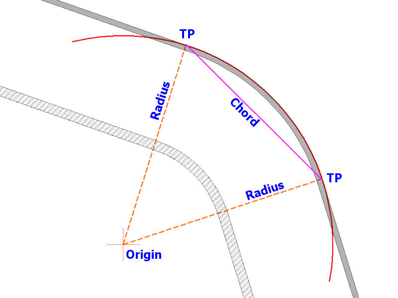
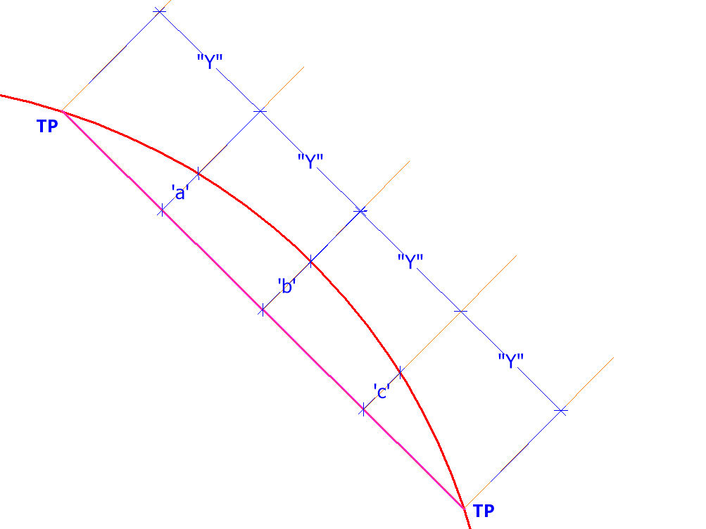
A chord (magenta) is created between the two Tangent Points (TP) and equally sub-divided into a number of equal segments each of Y metres. In this case, we've opted to divide the chord into 4 equal sections.
The perpendicular distance between the chord (magenta) and the arc (red) is measured on the plot at each of the three segment lines and recorded as values a, b and c.
The whole arrangement can then be recreated on site, by pulling a taut string line between the tangent points, marking the section lengths (Y) along that line, and then measuring the offsets (a, b and c) to give points on the required arc.
Calculate and Transfer
Again, this method uses chords subtended from the two tangent points, but this whole process can be carried out on site rather than in the office. The first chord is created by stretching a string line between the two tangent points. The mid point of the chord is established and marked and then the offset from the mid-point of the chord to the arc can be calculated using basic trigonometry.
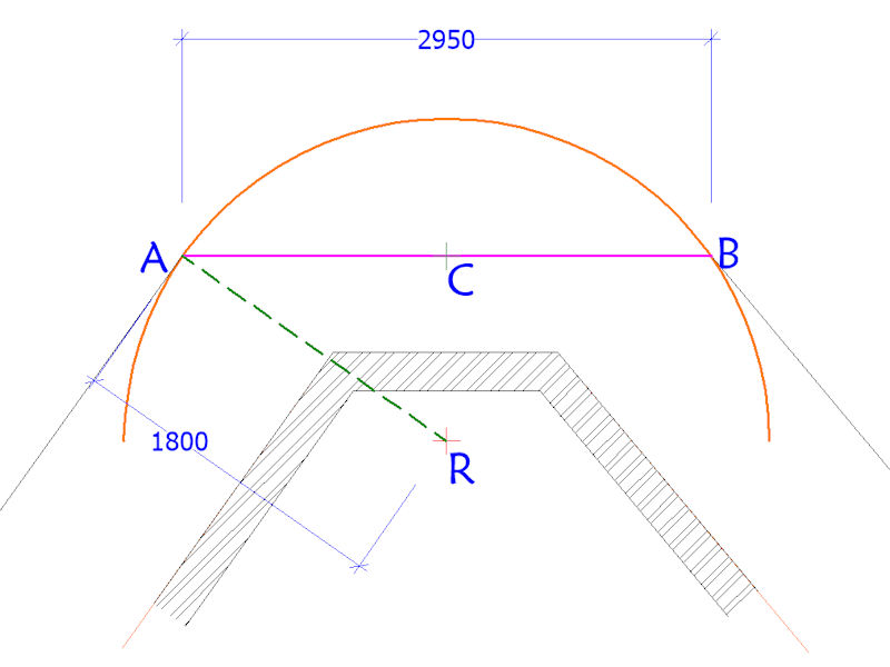
An arc with a radius of 1800mm has its origin (R) obscured by a building. The arc links two tangent points labelled (A) and (B). A chord (AB) is created between the two tangent points and when measured is found to be 2950mm in length. The mid-point of the chord is determined and marked as (C).
This creates a right-angled triangle ACR and it is known that AR=1800mm and AC= half of 2950mm = 1475mm.
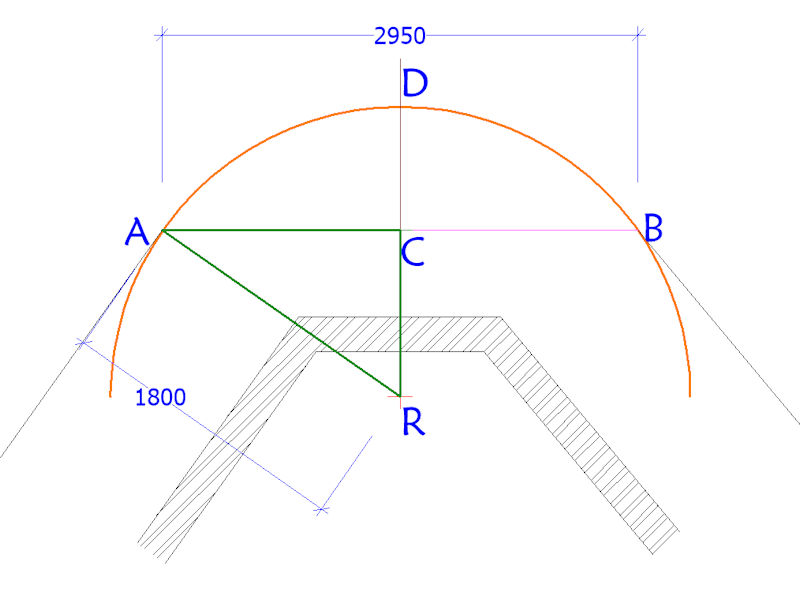
Using Pythagoras...
(AR²) = (AC²) + (RC²)
or
RC = √(AR² - AC²)
therefore...
RC = √(3240000 - 2175625) = √(1064375) = 1032mm
Given that line DR is a radius of the arc and therefore measures 1800mm, it can therefore be calculated that CD, the offset of the arc from the mid-point of chord AB is....
1800 - 1032mm = 768mm
...so, a perpendicular can be established from point C on the chord and point D on the required arc established and marked with a line pin.
This simple procedure can be repeated again to determine further points on the arc, as follows....
A new fixed point on the arc has now been established at point D. A new chord can be created between A and D, and, when measured, this is found to be 1664mm in length.
The mid-point of this new chord can be determined by measuring from A (or D) and then labelled as (E). This creates a yet another right-angled triangle AER and it has already been noted that AR=1800mm and we can calculate that AE= half of 1664mm = 832mm.
Again, using Pythagoras...
RE = √(AR² - AE²)
therefore,
RE = √(3240000 - 692224) = √(2547776) = 1596mm
Line FR is a radius of the arc, ie, 1800mm, and so line EF, the offset of the arc from the mid-point of chord AE is....
1800 -1596mm = 204mm
A new perpendicular can be created from point E on the chord and consequently point F is established and marked with a yet another line pin.
This procedure can be mirrored on the other side of the arc, that is, along a chord subtended from DB, and we then have the two tangent points plus 3 alignment points set out along the arc.
While these 5 reference points would be adequate to set out a relatively small radius arc such as this 1800mm example, for larger arcs more reference points could be needed to ensure accuracy. This can be done by repeating the above procedure, subtending new chords and establishing further points as many times as is required.
In this current example, the next chord would be subtended from AF to create point G, calculate the distance from mid-point H to G, and so on and so forth.
Inverse radius
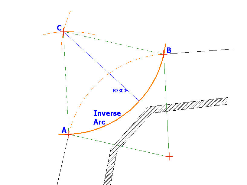
In this example, the origin point (R) of the required arc is again inaccessible, However, there is plenty of free space in front of the arc and so an 'inverse arc' can be created to aid setting out.
The radius of the required arc is to be 3.3 metres, and so, two new arcs, each with a radius of 3.3 metres, are swung from the tangent points at (A) and (B) and the point of intersection, (C) is marked with a line pin.
Next, a further arc of 3.3 metres radius is created, originating from intersection point (C) and intercepting tangent points (A) and (B). This is labelled as the 'Inverse Arc' on the diagram below.
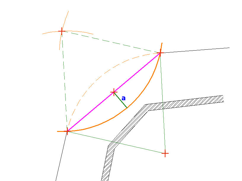
A chord (shown in magenta) is created between the tangent points at (A) and (B) and the centre point of the chord is marked. A perpendicular line from this centre point to the Inverse Arc can be measured and recorded as 'a'.
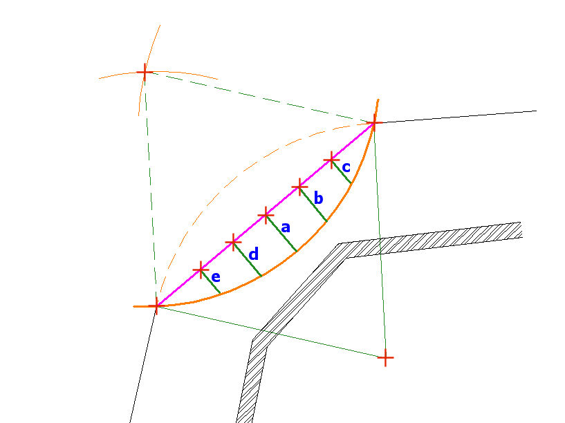
The chord (magenta) can be sub-divided into segments of suitable lengths - whatever suits the site and the size of the arc being created. Then, a series of perpendicular offsets from the chord to the inverse arc (shown as thicker green lines) can be measured and then immediately transferred to the opposite side of the chord to give a point position on the required arc. So, the measured offset (a) can be transferred to (a'), (b) to (b'), (c) to (c'), (d) to (d') and (e) to (e'), giving, in this example 5 reference points (marked by red squares) for the required arc.
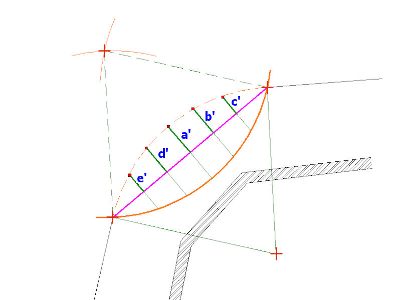
This is an eminently simple solution and can be used with arcs of any size simply by creating additional perpendiculars from that chord between the tangent points.
Never let them tell you that geometry is boring!