Introduction:

For this case study, the Recess Tray Cover was supplied by those nice people at Clark Drain , and the actual fitting was undertaken by the illustrious Mr John Higgins of Aintree Paving, in Liverpool. We used a Clark Drain 450mm "Square to Round" Cover and Frame (the part number is CLKS 450SQ/RD if you're really keen!) that have been specifically developed for fitting to circular ICs. Other covers are available from Clark Drain for fitting to square or rectangular access chambers and manholes, and there are a variety of different sizes.


Although the principles illustrated here can be adapted to many similar projects, it's worth noting that we were lucky (from John's point of view, at least!) that we didn't need to construct any regulating brickwork to build up the level of the chamber to meet the frame. This type of construction may be covered at a later date, but, for now, the basic principles of brickwork are given elsewhere on this website and some general information on using regulating brickwork is given on the main Manholes and Inspection Chambers page.
Preparation:
Recess Tray Covers are most commonly fitted once the bulk of the paving has been laid, but before final cutting-in and consolidation . This way, the contractor can make sure that the cover fits the pavement, and not t'other way round, where the paving is twisted this way and that to tie-in with a cover that's been laid at the wrong level.
On this job, the paving immediately surrounding the IC has been omitted, but the existing cover has been left in place to keep the chamber clean and free from debris during the other construction work.
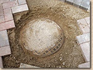
The first task is to clear around the cover, making sure there is ample working room, and exposing the concrete surround to the IC that should be there, just below the level of the existing cover. Again, the cover is left in place while this work is carried out so that no debris falls into the chamber during the preparation.
Some of the paving that had been laid is found to be obstructing the working area, so it's taken up and set aside for re-laying later. John excavates all around the IC, until the concrete surround is exposed, and there is plenty of room for the frame to be placed.
It should be noted that not all of these ICs have a proper concrete surround. On some jobs, they are simply backfilled with the excavated material. While this is not a serious problem on private driveways, it's not perfect, and it means extra work for the contractor, who will have to excavate the backfill material to a depth of 100-150mm and replace it with fresh concrete. Simply bedding the frame on 20mm or so of mortar over an uncertain fill material is not acceptable.
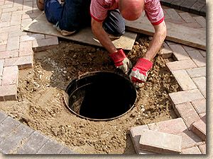
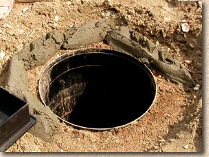
Once the area is clear and all loose material has been removed from around the old cover, it can be removed, along with its frame. The new frame is offered up to the top of the IC, to ensure there is enough room for it to fit.
On some installations, the level difference between the base of the new frame and the top of the IC can be a problem, and regulating brickwork or an additional Raising Piece may be required to accommodate the frame safely.
As a rough guide, a level difference between frame base and top of IC of less than 25mm can be accommodated with mortar. For a difference between 25mm and 70mm, a combination of mortar and acceptable packing materials should be used. The packing material must be an inert, solid material, preferably a stone of some type, such as slate, roofing tile, flagstone or brick. These should be built in such a way that no mortar bed is deeper than around 20mm.
Where a frame needs to be fitted at a gradient, such as on a sloping pavement, then it may be necessary to use a combination of materials, with, say, slate used as a pack at the lower end, slate, tile and pieces of flagstone used on the sides, and then brickwork used at the higher end.
For any level difference greater than 75mm, brickwork or a raising piece should always be used.
Placing the Frame
A bedding mortar is prepared. For bedding IC covers, a Class II mortar should be used and a splash of plasticiser will make the mortar easier to work when the frame is placed.
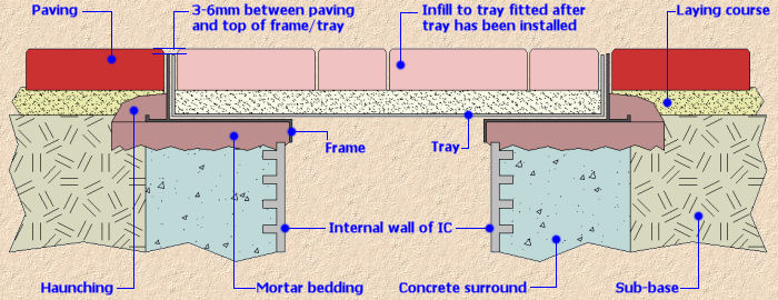
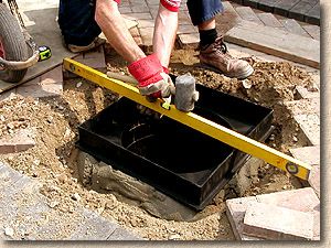
The mortar is spread over the concrete surround to a depth of around 40mm and the surface rippled with the blade of the trowel to provide a degree of 'give' for when the frame is placed. The mortar is spread approximately 50-100mm wider than absolutely necessary at all 4 edges as this will form part of the haunching once the frame is established.
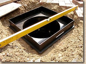
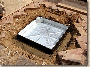
The frame is then bedded onto the mortar, aligned so that it sits directly over the inspection chamber. With this special "Square to Round" type of frame from Clarksteel, the base plate of the frame needs to be positioned so that the 'hole' tallies with the internal face of the chamber itself, before being tapped down to level using a hammer or a rubber mallet.
A long spirit level or straightedge timber is used to check the level against that of the paving. It's important to understand that the paving has yet to be consolidated, and so will be 5-8mm or so 'proud', until the time comes to compact the completed pavement. Further, it's standard practice for "ironwork" (the name given to all metal drainage fittings, including manhole covers, gratings and stop tap boxes) to be set 3-6mm lower than the finished paving level, so, overall, the frame for this recess cover needs to be 8-15mm lower than the current paving level.
By checking with the straightedge/level in several directions - up and down (longitudinal), side to side (transverse) and the two diagonals - John uses his experience to judge the 'best fit' level.
Once the level of the frame has been established, its alignment needs to be checked. The idea behind recess tray covers is that they should be as inconspicuous as possible, and so, by orienting the frame to suit the pattern of the paving, we can avoid the "sore thumb" syndrome. This driveway is being laid to a 45° pattern, so, in theory, we could set the frame to 45° so that it is aligned with the patterning, but this would look odd, as our ordered minds tell us that the cover should be "square" to the driveway, and so the alignment is carefully checked to ensure the frame's longitudinal edge is parallel to the soldier courses.
Haunching
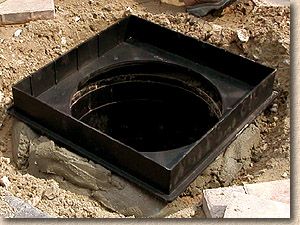
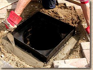
Once that's done, the haunching can be put in place. As this is a private driveway and we expect only light traffic, more of the bedding mortar can be used. Recall that we made the bedding much wider than the frame, and now, the mortar haunching extends from the bedding, up and over the flange on the base of the frame. There needs to be sufficient hanching to hold the frame securely, but not so much that it would interfere with the subsequent cutting-in of the paving around the frame. The haunching mortar is smoothed with the trowel to ensure it is compact and that any water finding its way onto the haunching will drain away.
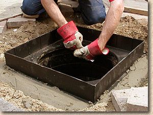
The gap that remains between the base of the frame and the top of the IC on the inside of the frame is then sealed with yet more mortar. The mortar can be forced into the gap from the blade of a trowel, or simply 'gloved' into place.
Although there is adequate mortar beneath the base plate of this frame, sealing this small gap ensures that should any remedial or maintenance work be carried out on the drains at some later date, there is nowehere for foul water (or worse!!) to lodge.
Care is needed to ensure that no mortar is left 'proud' as this could prevent the tray from sitting snugly inside the frame.
With frames that are not specially adapted to suit circular ICs, or with some frames being fitted to rectangular openings, the inside of the frame will need to be benched . This involves using mortar, or, preferably, a granolithic mortar , to form a smooth surface (the bench) with a gentle gradient between the internal face of the frame and the top of the IC. The advantage of these "Square-to-Round" frames from Clark Drain is that eliminate the need for costly and time-consuming benching.
Fitting the Tray
All that remains to be done is to fit the actual tray. The base plate of the frame needs to be checked for any grit or particles that might interfere with a snug fit, and any mortar or other detritus that may have fallen into the chamber during the fitting procedure needs to be cleaned out and the chamber rinsed clean with water.
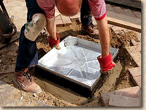
The tray is lowered into the frame evenly. The frame on the Clarksteel model features special spacer lugs which ensure the tray sits neatly, but that the risk of jointing sand becoming trapped between frame and tray, which can cause the tray to become 'locked in' when it happens with rigid all-steel frames and trays, is greatly reduced.
And that's it! The frame should be left for 24 hours at least before fitting the infill paving, to ensure the mortar has sufficient time to undergo initial setting, but, once the mortar/concrete is hard, the paving can be pieced-in outside the frame and then the paving within the tray itself cut to match the pattern of the paving before being fitted.
Finishing off
In an ideal world, the recess cover should not be subjected to a vibrating plate compactor for at least 5 days, to ensure the mortar/concrete has a decent chance to set, but this is not always possible, and it's often only 24 hours between the cover being fitted and being pieced-in and consolidated. In such a situation, it's worth lifting out the tray on completion, just to check that the seal between frame and IC remains sound. If it has developed a fracture, it can be patched there and then, but if there is any serious movement or loss of bedding, then it may need to be lifted and re-fitted.
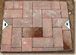
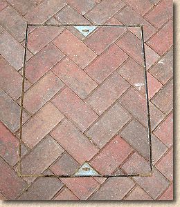
Finally, here's a couple of trays from the same job that were cut-in previously. The first is a 90° herringbone and the tray has been lifted out of the frame while maintenance is carried out on the drains. In the second, a 45° herringbone, notice how the cover has been aligned 'square' with the pattern, but the cutting has been quite a complex procedure to maintain the patterning.