Installing additional drainage
Often, the construction of new paving or extension of existing paving requires the installation of additional drainage. While the Fittings page deals with gullies, hoppers and the like for collecting the surface water and channelling it into the drainage system, this page looks at how those fixtures and fittings are connected to an existing system, while the following page considers Manholes and Inspection Chambers .
There are 4 ways to connect new drainage to an existing system:-
- - via a new branch junction or access chamber to an existing pipeline
- - via a saddle onto an existing sewer
- - via an existing manhole or existing inspection chamber
- - via a new inspection chamber or new manhole
Connecting to foul or combined systems:
The connections shown on the remainder of this page assume that a surface water fitting, such as a gully , hopper or rainwater pick-up , is being directly connected to a surface water system.
There are instances when, for reasons that we need not explore at this point, a surface water fitting is connected to a combined or a foul system.
Whenever this occurs, the connection MUST be trapped to prevent the escape of nasty odours and potentially dangerous sewer gases.
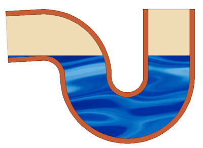
In this definition, a 'trap' is a simple but effective barrier to the venting of gases from an underground pipe system.
The simplest traps are available as manufactured fittings, such as a P-trap or a S-trap, but there are also gullies that have traps built into them.
It matters not which form of trap is used, as long as there is one. Different situations will demand different solutions. There is no single right answer. As long as a trap is present, it is the right solution.
Branch Junctions
Branch junctions are a simple and cheap method of connecting a new drainage spur to an existing line. However, they do not enable access to the system for maintenance and/or cleaning and so should only be used with suitable access fittings or for spurs terminating with a rodding eye. For spurs where access is required via the junction, consider the use of an access chamber, as described below.
There are two basic forms of branch junction, determined by the angle of the incoming spur, namely oblique or square. These are shown in the diagram opposite. Oblique junctions have the spur joining the main channel at approximately 45° while square junctions have the spur coming in perpendicular (90°) to the main channel, although this is 'softened' by the adjoining spur being slightly curved. Branch junctions may be single or double affairs, depending on the number of spurs to be connected to the main channel.
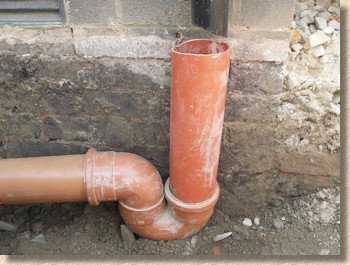
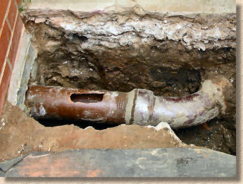
The illustration above depicts how a new drainage spur can be connected directly into an existing underground pipe by breaking into the pipeline and installing a branch junction. The section of pipe to be removed is best cut out with a power saw, so ensure you have ample working room. Cut out a section 10-15mm longer than the length of the branch junction.
The new junction itself is inserted in exactly the same manner as shown below for inserting an access chamber .
Access Chambers
These access fittings are ideal for making single connections, and by using raising pieces, they are suitable to a depth of around 600mm. They typically have a lightweight aluminium cover and cost around £40. They should be set to level on a 100mm thick concrete bed but do not normally require a concrete haunch before backfilling. They come with one or two side inlets set at a variety of angles to suit most situations. Generally 300-450mm in diameter, and 225-300mm deep, with raising pieces generally 225-450mm deep.
Installation
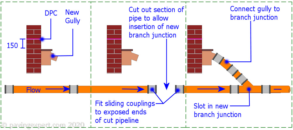
Both access chambers and branch junctions can be 'inserted' into an existing pipeline by using sliding or adjustable couplings. A sliding coupling is a normal coupling without the central register. This allows the coupling to be slid completely onto an existing pipe, unlike normal couplings in which the central register ensures the coupling is positioned correctly when joining two pipes.
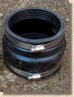
An adjustable coupling (also known as a "Universal Coupling") is a bigger and more expensive affair. They have adjustable collars at each end of the coupling, which are tightened by means of a large 'Jubilee Clip'. They are ideal for awkward connections, or for connecting two different types of pipe.
The process of installing an access chamber is illustrated in the animation opposite. Note that a branch junction can be installed using an identical process.
The couplings will slide quite freely as long as the pipe is well greased with pipe lubricant. If difficult, use a lever, such as a nail bar or spade, anchored into the bed, to push the coupling onto the access chamber.
If using adjustable couplings, they should be tightened up via the worm-gear before backfilling.
The process of installation is slightly different for the plastic inspection chambers (commonly abbreviate to IC) than for the simple access junction illustrated above. Because an IC has inbuilt couplings, short lengths of pipe, 300-600mm long and known as 'rockers', have to be used to connect the IC to the inlet and outlet of the existing pipe.
These plastic inspection chambers are further discussed on the Manholes page.
Once installation is complete, raising pieces can be added to an access or inspection chamber as required and the cover fitted. The new spur can be connected up to the new drainage point via straight pipes, bends and couplings as required. Any testing required should be undertaken before the backfilling is done in layers 150-225mm thick, each layer being compacted before placing the next.

A photo case study following the step-by-step installation of an IC into an existing line of drainage can be found on this page . The case study follows the insertion of an IC to provide a new connection for additional drainage.
Saddles
Saddles are a way of connecting to an existing pipe by actually breaking into the pipe via an elliptical or circular hole, rather than cutting out a whole section of pipe and replacing it with a branch junction, access chamber or IC as discussed above. Generally speaking, only pipes of at least 150mm diameter are 'tapped' for saddles, and more often, it is the larger pipes, diameter 225mm or more, that are considered to be viable candidates for a saddle connection.
Pipework connected via a saddle is always of a smaller diameter than the receiving pipe. For instance, a 100mm diameter pipe may be saddled on to a 225mm diameter but a 225mm pipe would NEVER be saddled onto a 150mm pipe.
A saddle is most commonly tapped into the crown, that is the uppermost surface, of a pipe. A starter hole is made in the receiving pipe, and then enlarged until the spigot of the saddle just fits into it and sits comfortably atop the receiving pipe.
On clayware or concrete pipes, creating the hole is a fairly skilled job; on larger pipes, a core-cutter may be used to drill a receiving hole, or a series of smaller holes, say 10mm diameter, may be 'stitch-drilled' to the required perimeter of the hole. On smaller pipes, especially 150mm and 225mm clayware, the hole is normally started with a transverse cut made by a power saw and gradually enlarged with a small hammer. Extreme care needs to be exercised to avoid fracturing the pipe, which would then need to be removed and replaced, a possibly expensive operation.
Plasticware pipes are much simpler to tap, and less liable to fracture. A starter hole is created with a power drill and then a jigsaw or hacksaw blade can be used to enlarge the hole to the required size.
It is essential that a saddle connection is properly sealed to the receiving pipe to prevent ingress of debris and egress of effluent. With clayware saddles, a mortar joint is usually created, bedding the saddle onto the receiving pipe, and then haunching and backfilling around the saddle with concrete. Plasticware saddles vary between manufacturers; some are solvent-welded, others incorporate a collar that encircles the receiving pipe. In all cases, guidance given in the manufacturers literature should be followed to the letter.
Note: Manholes and sewers are exceptionally dangerous places. Noxious gases may be present that can injure and kill. It is most strongly recommended that all work on live sewers is undertaken by drainage specialists who have successfully completed a 'Confined Spaces' and/or 'Sewer Working' safety course rather than diy'ers. Properly trained and accredited tradesmen will have certificates to prove their competence. DO NOT TAKE RISKS.
SUDS Pages