Principles
Land drainage is principally used to alleviate waterlogging in fields and gardens, but it can also dessiccate certain ground types in prolonged dry spells, so think carefully before installing. Note that land drainage is NOT the same as a soakaway, although they may both be used to dispose of surface and/or ground water. Click here for the soakaways page.
If you are looking for information on waterlogged gardens, you may be interested to read the Improving Clay Soil FAQ written by this site's author for uk.rec.gardening , a usenet group dedicated to the discussion of all things connected with gardening in Britain and Ireland. Click here to open the faq in a new window.
Other uses for land drainage are as dispersal drains for septic systems and as collector drains where more formal drainage fittings would be inappropriate. It is also an essential part of civil engineering projects, where the use of fin drains and drainage composites is gradually replacing the more traditional forms of land drainage.
Land drainage works by providing an open conduit for groundwater to follow to a disposal point, or, in the case of dispersal drains, to a dispersal area or leach field. There are a few variations on this theme, involving the type of backfill material, and the type of pre-formed conduit that is used, but all rely on two simple principles; that the land drain provides a 'path of least resistance' for groundwater to follow, and that, left to its own devices, water flows down even the gentlest of slopes.
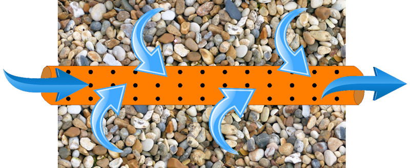
Groundwater is held by soils within pores, which are the small voids or interstices between the grains that make up the soil. The bedding material surrounding a land drain has significantly larger pores between each stone, providing more space for the groundwater to occupy. The centre of the pipe itself can be thought of as one big pore. Therefore, in a collector drain, there is a 'gradient' of hydrostatic pressure from the soil, via the bedding into the pipe, along which the groundwater will migrate to the point of lowest hydrostatic pressure, ie, the inside of the pipe.
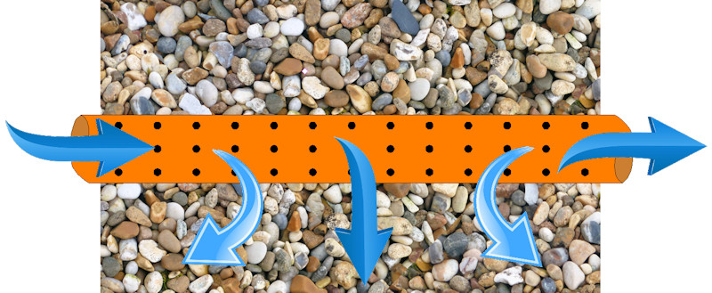
In a dispersal drain, the gradient is reversed because water is being continually added to the pipe from the septic tank or other source, and so the hydrostatic pressure is greatest inside the pipe, causing the flow to be from pipe to soil, rather than from soil to pipe.
Soil mechanics and hydro-dynamics is a major field within the discipline of civil engineering and is far beyond the remit of this site, but, hopefully, this will have given some insight into the basic principles involved in groundwater management.
The disposal point of a land drain system, whether it's a manhole, a soakaway , leach field or an outfall , is always at the lowest point of the system. Try as we might, we haven't yet managed to get water to flow uphill!
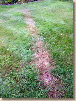
During the Summer, land drainage can sometimes be identified by parched growth of vegetation over the line of drainage. However, this phenomenon may be reversed in situations where land drainage has been used to disperse the processed effluent of a septic tank, where surface vegetation, trickle fed by a near constant stream of nutrient enriched moisture, is that bit more lush.
Types of Pipes
Most land drainage systems consists of lengths of perforated or slotted plastic or clayware pipe laid in a trench with a porous surround. There is a wide range of sizes, from 80mm flexible plastic, up to 1000mm or more for large agricultural or commercial schemes, and they come in a wide variety of materials, including uPVC, clayware, fibre-cement, concrete and ductile iron.
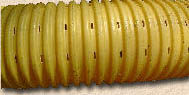
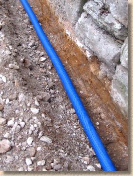
80mm diameter perforated flexible/corrugated plastic pipe is ideal for garden drainage. Larger diameters are also available and they are typically used on larger schemes, such as carriageway edge interceptor drains. The smaller flexible plastic type is readily available in 25m coils from your local builders' merchant at around £1-2 per metre. It is very simple to install, well within the capabilities of a DIY enthusiast. This type of land drain has holes or perforations around the entire circumference, so there is no 'top' or 'bottom'.
Rigid land drain pipes may be fabricated from clayware, plastic or other some other solid material. Some types will be perforated or slotted around the entire circumference while others will be 'half-perforated', ie, have holes on only one face of the pipe. As with their non-perforated cousins, rigid land drain pipes are normally joined together by means of a coupling, although some systems use 'sockets and spigots'. See Drainage Installation page for more details on couplings.

As mentioned above, there are a variety of different types of land drain available. Clayware and rigid plastic perforated pipes are generally more expensive than the flexible type and they should always be used where a land-drain passes beneath a trafficked area, such as a driveway, or where the depth of the drainage is such that the weight of the backfill material would cause a flexible plastic pipe to collapse. As a general rule of thumb, we do not use flexible plastic pipe at depths greater than 1.2m.
And don't be confused by colour. Some pipes may be yellow, white, blue, black or faux-terracotta. It means nothing: once buried, they are all just pipes!
Theoretically, a rigid perforated clayware land drain could be used at depths up to 6m, but this would require machine excavation and shoring, and is best left to professionals.
Historic land drains
Clayware pipes
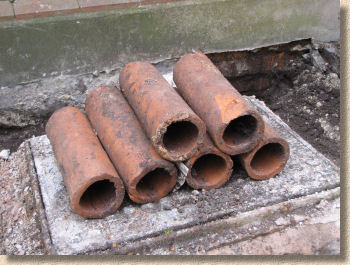
Land drains or field drains or field tiles as they are variously known have been used for hundreds of years and, historically, they didn't rely on perforated pipes.
The most commonly encountered 'historic' version is the field tile - so historic it was still being used in the 1960s! These consisted of nothing more than short lengths (12"-18" or 300-450mm) of fairly crudely formed plain-ended clay pipes with a diameter of anywhere from 2½" - 5" (65mm to 125mm) which were butted up against their neighbours in a basic trench, all too often with no gravel surround, and then covered over with the excavated material. They were, as the name suggests, commonly used to aid drainage in soggy fields and many of them have carried on that function for decades without a problem.
Occasionally, they can be found silted-up, which is often a result of the outfall being blocked or obstructed in some way rather than any real problem with the pipes themselves, which were nearly always laid to a respectable gradient of 1:60 or thereabouts.
They are sometimes encountered when landscaping works are undertaken on a property. Sometimes, there are remnants of an old field drain system that was left in place when the land was originally developed, but in some cases, particularly with pre-war houses, they were deliberately installed as an aid to drainage for lawns or gardens.
French Drains
Another commonly encountered form of land drainage from the days of yore is the so-called French Drain, which is essentially nothing more than a gravel-filled trench. Nowadays, the industry prefers to use Fin Drains which are much more reliable.
A big part of the problem with French Drains was that the vast majority of them were poorly constructed. As already stated they often comprise nothing more than a trench backfilled with any old gravel that happened to be lying around, but a true French Drain should include an unjointed pipe and the better ones would be surrounded by a graded filter of selected gravels and sands.
Roman Drains
There is archaeological evidence to show this type of drain in use over 2,000 years ago when it was probably part of a combined system, carrying surface water and foul, and they can occasionally be found, still functioning, on properties dating to the 17th - 19th centuries. However, in some parts of the country where flagstone was more readily available than gravel, they were sometimes used as a crude land drain.
The structure is pretty basic. There would usually be a flagstone base (invert) with parallel stone edges and then a flagstone cap, all of which served to create a rectangular-section 'hole' through which water and worse could flow.
Dealing with them:
Before discarding any historic land drain or blocking them off, it's best to ensure they are actually redundant. In extended rain-free spells, they can sometimes seem dry and unused, but are actually working, and working well, once the rain (inevitably) returns. They should be tracked, if at all possible, using drain rods or cctv, to determine whether or not they can be disregarded or whether, in fact, they'll need to be repaired.
A drain which is demonstrably capped-off or breached at both ends of a run can be disregarded or removed. However, if there is even the slightest suspicion that the drain is functioning, then it's best to replace it with a modern equivalent, either a perforated pipe or a filter drain as appropriate.
Construction

A "case study" following the installation of a land drain to a private garden can be found here
Land drainage systems rely on a combination of gravity and hydrostatic pressure to create a flow within the pipes. Systems are typically installed with a gentle slope in the region of 1:100-1:200 towards the outfall or disposal point. For this reason, it is best to lay land drainage 'uphill' i.e. start at the outfall, which should be the lowest point on the land drainage system.
The trench width is usually calculated as external pipe diameter (abbreviated to OD, as in Outside Diameter) plus 150mm sidefill to each side, so, for a pipe with an OD of 115mm, the trench width would need to be....
115 + (2 × 150) = 415mm
The trench should be excavated in advance and lined with the geo-textile if one is to be used. The bedding material is placed in the base of the trench, then the pipe itself laid and checked for alignment and gradient before the sidefill is added and finally the backfill.
Ensure a clean gravel is used for the surrounding material, and do not use limestone chippings unless nothing else is available - Limestone can precipitate calcium carbonate in wet conditions, depositing minerals that can clog up the drain. Make sure there is at least 75mm of gravel around and above the perforated pipe. The geo-textile filter is not essential, but will prolong the life of the drain by filtering out smaller clay and soil particles, and deter thirsty roots from seeking refreshment in the land drain. Small rootlets in a land drain can quickly expanded to a pipe-blocking mass!
Technical Notes:
In the diagrams above, the "Selected Free Draining Material" shown in the Filter Drain construction is a fairly loose term. For smaller applications, such as gardens and private houses, it could be almost any gravel or coarse sand, a crushed rock, or any material that could be considered 'free draining'.
For commercial or civil applications, then most specifications would tend to use a "Type B Filter drain material" for this layer, as shown in the table opposite. Note that Type A material is much finer than Type B. Type C designation is intended for special applications where local materials might be used.
Holes up or Holes down?
Half-perforated pipes are laid 'holes up' or 'holes down' depending on their intended use - see diagram. In most applications, the pipes are laid with the holes to the bottom of the pipe; the hydrostatic gradient discussed above ensures that the pipe functions as a conduit for groundwater. For collector drains, however, or for systems that are connected to conventional drainage systems, the pipes should be laid with the holes uppermost.

Holes at bottom

Holes at top
Any trench deeper than 1.2m must be shored-up; trench walls can collapse without warning and can seriously injure or kill any persons trapped beneath the fall. If in doubt, shore it up!
Making Connections
Some land drainage systems have their own range of couplings, fittings and adapters, but most of the rigid systems use fittings from that manufacturer's standard sewer range. So, for instance, a perforated clayware pipeline will use a standard clayware junction to adjoin another line of land drainage.
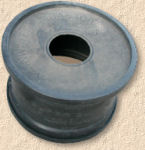
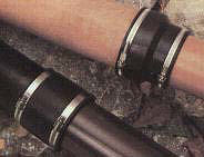
However, some manufacturers do supply cheaper couplings for their land drainage ranges, as there is no requirement for couplings to be watertight, as they must be in the sewer ranges. Typical couplings for flexible plastic and a clayware pipe are shown opposite. They tend not to have an 'O' ring present, as would be expected in a standard coupling, and they do not need lubricating to aid insertion, as they tend to be fairly loose fitting.
Land drainage can be connected to the standard drainage of a surface water sewer in a number of ways. Catch pits, the preferred method, were discussed above , but where a catch pit is not feasible or deemed not necessary, direct connection can be made...
- via a standard coupling
- via an adaptor coupling
- via an adjustable coupling
- direct into an inspection chamber
Standard couplings can be used to connect rigid systems with their surface water sewer pipe cousins, which use the same couplings.
Adaptor couplings are more normally used for connecting to downspouts to the surface water system. They consist of a standard 'O' ring coupling on the downstream half and a flexible rubber skirt on the upstream half, that is stretched around a downspout (or, in this case, the flexible land drain), giving a snug fit.
Adjustable couplings rely on a 'Jubilee Clip' type fitting on both ends of the coupling which are adjusted as required to suit the pipe being connected. They are relatively expensive, and normally used to connect different types of pipe, eg, Cast Iron to Clayware.
Direct connection into an inspection chamber is dealt with on the Manholes page.
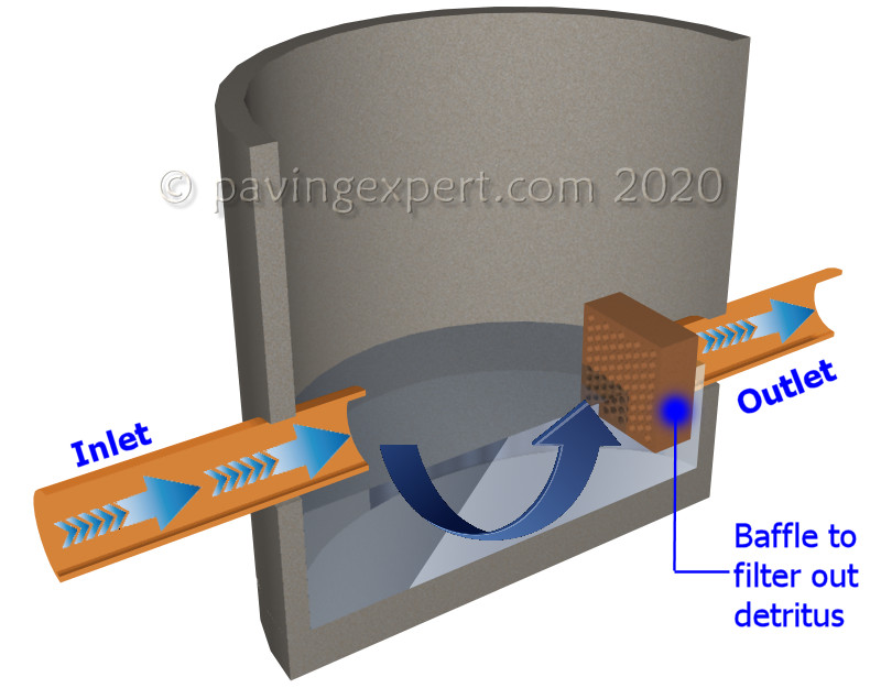
Catch Pits
Also known as an Interceptor, Interceptor Pit or Silt Trap
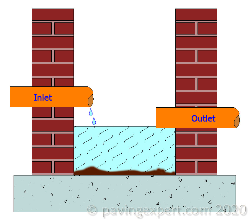
On filter/collector land drainage systems that have not used a geo-textile to minimise soil particle or sediment migration, a catch-pit or silt trap should be considered preceding any outfall to a natural watercourse or sewer system, to remove grits, silts and excess sediment. A catch-pit is, essentially, an empty chamber with an inlet pipe and an outlet pipe set at a level above the floor of the pit. Any sediment carried by the system settles out whilst in the catch pit, from where it can be periodically pumped out or removed.
Outfalls
Land drainage, whether it has been installed in order to drain an area of soggy ground, or to disperse water collected from hard surfaces or the effluent from a septic tank, must have an outfall, ie, a point where it can 'empty' itself.
Filter and collector systems (see below) often discharge, or "outfall", into a ditch or stream, but they can be connected to the surface water system of a property if there is absolutely no possible alternative, or if your local water board do not permit outfalls to natural watercourses. Only in the most exceptional of circumstances should land drainage be outfalled to a combined or a foul water system, and, if it is, the connection MUST be via a trap to prevent smells, effluent and/or raw sewage entering the land drainage system.
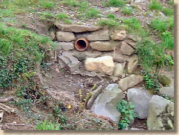
For outfalling to a ditch or other watercourse (assuming there is no problem with consent from the land-owner or water authority), the outfall pipe, preferably clay or rigid plastic, needs to be anchored into the bank with a large block of concrete. It's essential that the section of bank directly beneath the outfall pipe is adequately protected from erosion by means of a stone or concrete apron. A typical cross-section is shown opposite.
Most local authorities and/or water boards have their own specification for an outfall detail, but the illustration opposite shows the the type of scheme favoured by many authorities for small outfalls. Larger outfalls, such as those serving an extensive land-drainage or surface water system, those discharging into a fast-flowing watercourse or those with pipes of diameter greater than 225mm, may involve cast in-situ concrete structures and possibly steel piling driven into the river-bed. In all cases, consult your local authority before commencing work.
Land-drain layout
Where land drainage is used to drain a larger garden, it should be installed in the classic herringbone pattern to ensure no point within the area is more than 2.5m from a drain. Some pre-planning is essential to ensure the best use of the drain and to allow for unavoidable features such as trees, walls, etc., and to ensure that the drainage runs to a convenient outfall at an acceptable gradient.
When used to drain fields or other agricultural land, the distance between individual drain runs can be 10 metres or more, depending on local conditions. Such systems are almost always installed by specialist contractors, often on behalf of the local water authority, and a full survey is usually undertaken before the ground is opened.
Another use for land drainage in the garden is as a collector drain, installed as a single line, 300-450mm from the edge of a pavement to carry away the surface run-off and prevent the garden from becoming water-logged. In this sort of scenario, a decorative gravel can be used to dress the surface of the drain, making it a feature of the hard landscaping. See also Fin Drains
Leach Fields
Dispersal systems, as used with septic tanks, normally discharge into a "Leach Field" (aka an 'absorption field'), a special area downstream of a septic tank where the treated effluent is allowed to soak into the ground whereupon the treatment process is continued by soil-borne bacteria and organisms. The size/area of the leach field is determined by the percolation rate of the ground and the number of persons served by the septic tank. Unlike collector drains, dispersal drains tend to be installed as 'closed' systems, ie, there are no 'dead end' lengths of pipe - see diagram.
SUDS Pages