Working Lines and Levels
Setting line levels
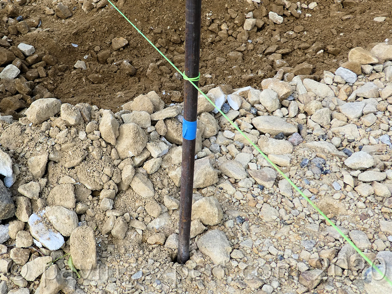
On the previous page , we set out the entire driveway with regard to shape. The pins have been positioned and the string line established so now we need to set the string line to the correct level at each pin. With the half-hitch knots, by pulling the string line on each side of the pin towards the pin itself, the tension on the half-hitch is reduced allowing it to be moved up or down the pin as required.
The drawing opposite shows that the part of the driveway nearest the house is going to be drained to the gullies at J and K, while the lower part of the drive is going to be drained towards the linear channel drain at the threshold with the public footpath. This leads to the creation of an imaginary 'change of fall' line between L and M, which explains the reason for the intermediate pin L on the straight line N-Q.
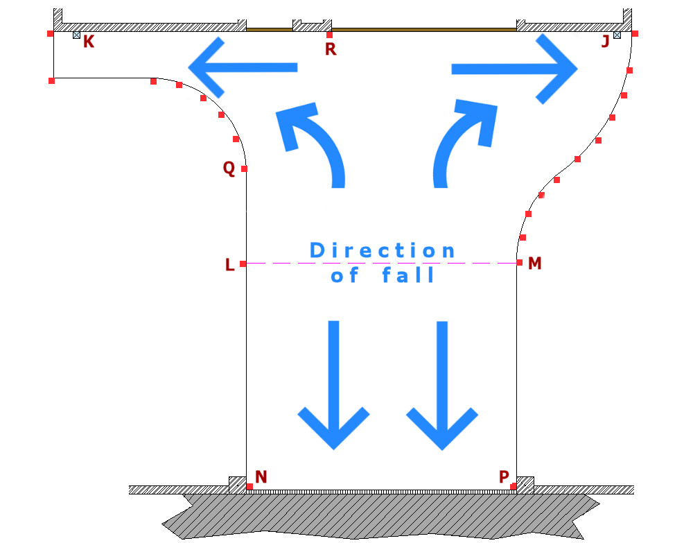
It can also be seen that the driveway needs to slope in two directions along the front of the house, with a high point at R and falling towards the gullies at J and K, respectively. We know that, as R is a point against the brickwork of the property, it cannot be any higher than 150mm below damp proof course (dpc), and so we can set that point immediately.
Calculating Falls
The concept of falls and gradients is explained more fully on this page
We also know that R is roughly equidistant between J and K, and so is approximately 7 metres from each gully. We need a minimum gradient of 1:80 to ensure surface water will drain on a block pavement such as this. Other surfaces, especially hand laid tarmacadam, need a steeper gradient than this, say 1:60, to ensure adequate drainage.
So, 7 metres at a gradient of 1:80 = 7.5 × (1÷80) = 7.5 × 0.0125 = 0.0875m = approx 88mm
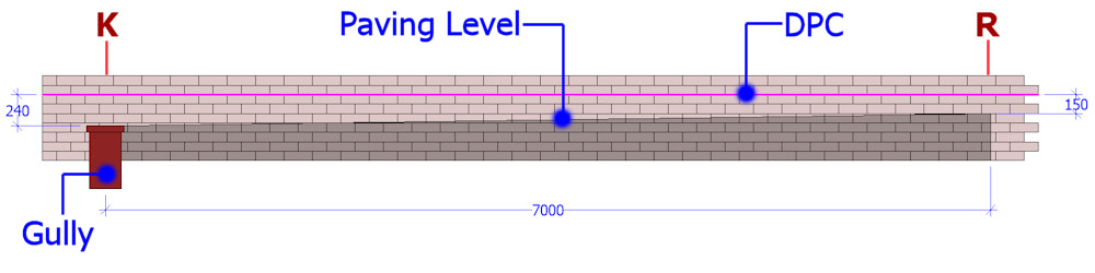
We now know that the level at the gullies must be at least 88mm lower than at point R, which has been established as 150mm below dpc, so J and K must be (150 + 88) = 238 mm below dpc (assuming dpc is level). We'll round-up to 240mm to keep things simple. Measuring down from the dpc, we can mark this level onto the brickwork, and adjust the gully levels to suit.
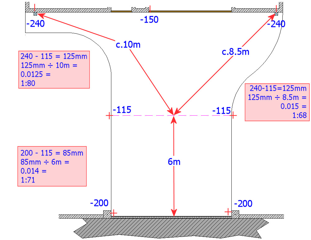
Now we have R, J and K established, the next critical levels to set are the high points on the driveway, on the break line L-M. We can measure that from the centre point of the break line L-M to the furthest gully, K, is approximately 10 metres. Using the standard 1:80 fall, we can calculate that the midpoint on line L-M needs to be......
10 × (1÷80) = 10 × 0.0125 = 0.125m = approx 125mm higher than the gully at K
We know that the gully at K is 90mm below R, so Points L and M need to be 125 - 90 = 35mm higher than point R, which means it would be 150mm - 35mm = 115mm below DPC level.
As stated in the brief given on the Setting Out Lines & Arcs page, we also know that the threshold level, N-P is 50mm lower than Point R, so there is (35+50) = 85mm of fall from points L and M to points N and P, a distance of only 6 metres, which is a fall of (85 ÷ 6000) = 1:71, well within our 1:80 minimum.
Level Transfer
This sub-section describes simple techniques for level transfer using everyday tools. For a more reliable and accurate approach, see the pages on boning rods and particularly automatic levels.
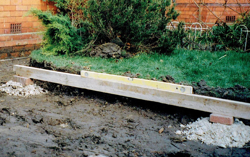
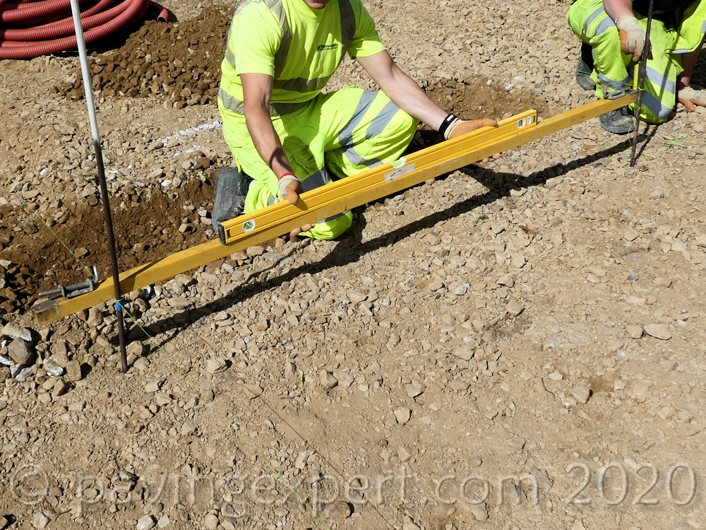
In the absence of an automatic or laser level, we can use a straight edged timber and a good spirit level to transfer the level from point R to points L and M, and then add 35mm. Small boat levels, 200-300mm long are not usually accurate enough for this sort of work, and so we recommend a spirit level at least 1200mm in length to be accurate when transferring the level by means of a straight edged timber, 3 to 4 metres in length. However, it is obvious that even a 4m straight edge will not span the distance from R to L or M, and so we set up a temporary intermediate level.
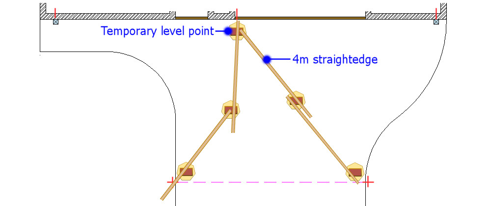
A brick is set on a sand bed at Point R so that its surface is at exactly the correct paving level, ie, 150mm below dpc. Another brick is then set up between R and L, also on a sand bed. The straight-edge is then placed to bridge the two bricks, and checked with the spirit level. The intermediate brick is tapped down until the spirit level tells us that it is exactly level with the brick at Point R.
The required 35mm uplift can then easily be measured onto the line pin at points L and M and marked as appropriate.
This method of level transfer is only suitable for use on small projects, and a level should never be transferred in more than 2 stages, to keep errors to an acceptable minimum.
By using an intermediate level transfer, we've now established the paving level at points L and M, and, from earlier, at points J, K and R. We have the level of the existing footpath to tie in to at points N and P, leaving only the levels to be set on the intermediate pins around the curves.
Setting Levels to Curves
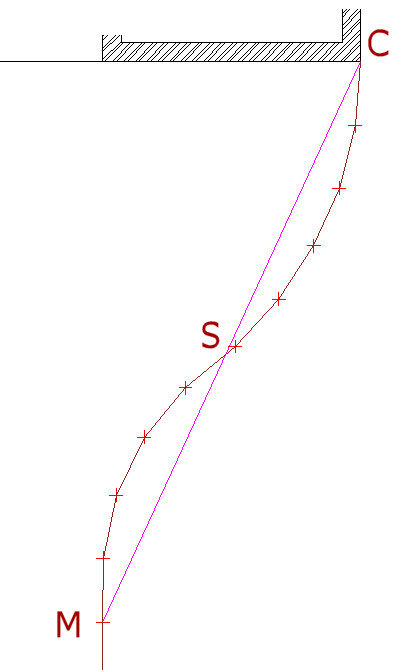
Dealing first with the S-curve on the right hand side of the driveway, by stretching a line between known point C and known point M, it can be seen that this temporary line passes very close to one of the marker pins at 'S'. The spirit level can then be used to transfer the level from the temporary line to the nearest pin.
The temporary line is then looped around pin S with a half hitch as shown above, and the spirit level used to transfer a level from the temporary string line to the intermediate pins at T and U.
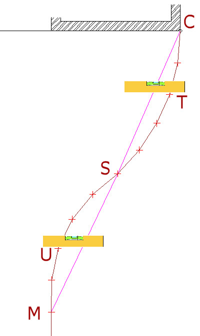
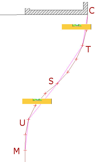
Once the string line is half-hitched around the pins at T and U, the process is repeated until the line level is set on every pin between C and M.
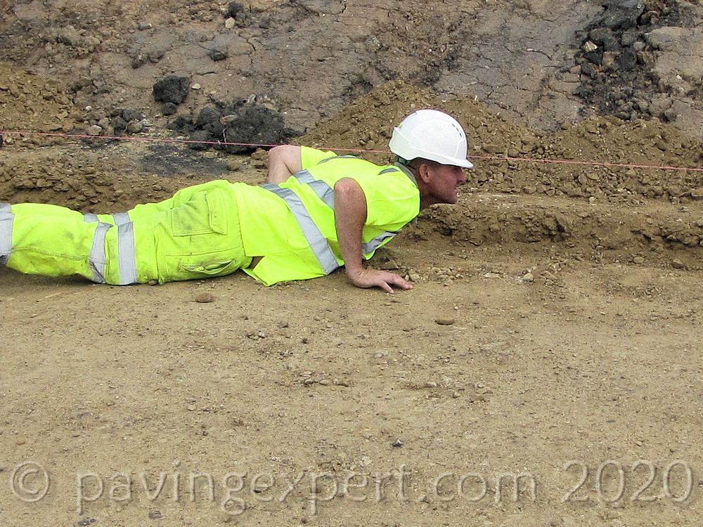
By lying flat on the ground, with your eye level with the string line, and looking along it, there should be no obvious high or low points as the line snakes its way around the pins from C to M. Minor adjustments to the level at each pin may be required to ensure the level is 'sweet' along the line.
When the levels are established on each pin, by repeated transfer as explained, the line can be set up permanently as a guide to paving level. In this scenario, the soldier course edges to the driveway will be laid on a concrete bed and tapped down until the top of the block is level with the taut string line.
Setting Intermediate Levels
The curve on the left hand side of the driveway, and the short access path along the front of the house will have levels set on them next, completing the last stage of the setting out work.
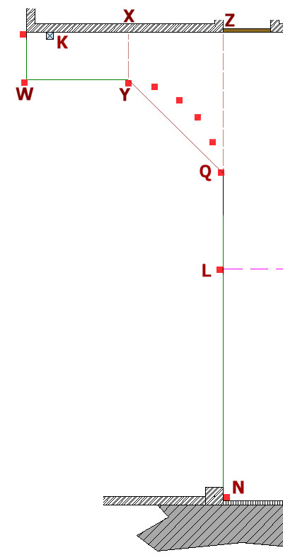
The curve itself can be set out using the principles described above for setting levels on the S-curve, but the paving level at Points Q, Y and W should be established first, reducing the amount of level transfer from string line required, and therefore maximising overall accuracy.
Firstly, Point W can be established by levelling across from the top of the gully at point K and allowing this 1.2 metre wide path to slope towards the gully by approximately 20mm, which is well within the 1:80 tolerance specified. So, point W is 20mm higher than Point K.
Point Y is similarly established, by levelling across from the line established between K and R at point X. However, at this point, we do not want the path to fall towards the house, as we did for the previous point, as there is no gully at point X. Therefore, we will set Point Y at 10mm below point X.
Point Q is established by extrapolating the line N-L until it intercepts the line K-R at point Z. The taut string line will just touch the pin at Q, which can then be marked for paving level.
The level for point Q is established by pulling the line tight from L to Z and marking the pin at Q precisely where it touches, so that the line L-Z is what is referred to as a 'flat bone' - a single plane, not necessarily "flat level", ie: no fall in any direction but a consistent, steady fall in one direction.
Bone levels are discussed in greater detail on a subsequent page.
Finally, the paving levels for all the intermediate pins on the curve can be transferred using the same method shown above for the S-curve, working from a temporary string line stretched between known point Q and known point Y.
Et Voila! The job is now set out for line and level. After a thorough check that the levels seem right and the alignment is true, the paving work can begin.