Introduction:
These procedures ensure a safe, accurate and aesthetically pleasing kerbline is achieved before the units are fixed in position with the concrete haunching . The laying process for kerbs and edgings is covered on the previous page .
Profiling refers to the adjustments in level that are done to create a smooth, flowing run of kerbs or edgings when viewed in section . Adjustments to the line of kerbs, to create a smooth, flowing run of kerbs when viewed in plan is known as Alignment .


Profiling
As discussed on the Drainage for Pavements page, all pavements (other than permeable pavements ) should be gently sloped to facilitate drainage of surface water to a disposal point of some description. In many pavements, there will be more than one plane, that is, some sections of the pavement will slope in one particular direction and other sections will slope in a different direction. This "change in gradient "or "change in fall" may be because the pavement needs to meet a fixed threshold or because it is following the natural lie of the land.
Deliberate profiling of the surface of an otherwise flat site is known as 'Summit and Valley' drainage, and drainage points, usually a gully of some sort, are located at the lowest point within the valleys.
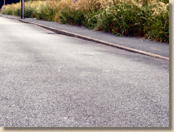
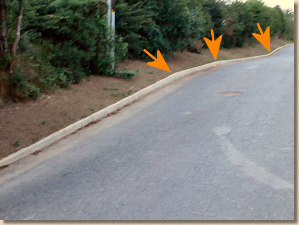
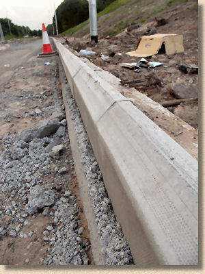
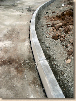
In the example shown opposite, the kerbline remains fairly consistent in profile but the macadam surface undulates to create longitudinal fall towards the gullies.
When the surface of a pavement exhibits a change in gradient, this may also be reflected in the edgings or kerbs.
However, the transition from one gradient to another should not be abrupt; it should be 'sweetened', that is, the change in gradient should take place gradually over an appropriate distance. Just what constitutes an 'appropriate distance' is determined by the size of the units being used and the size of the pavement itself. For instance, a change in gradient within a soldier course of paving bricks may be accommodated over a couple of metres, whereas a change in gradient within a line of road kerbs will probably take place over 8-10 metres. As a very rough guide, we normally find that a 'sweet' change in gradient can best be achieved by effecting the transition over 7-15 "units", whether the units be paving bricks, road kerbs or whatever.
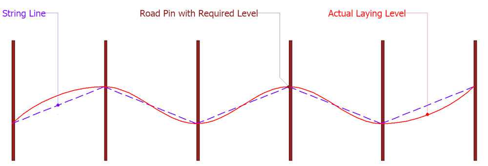
On site, the edgings or kerbs are laid so that they comply with the required levels at line pins or other fixed points, and the 'sweetening' occurs between these level points, as shown in the schematic above.
The required level at each line pin is established (see Setting Out page) and a taut string line (shown in blue) is fastened in place. When it comes to laying the edgings/kerbs, those units immediately adjacent to the line pins are laid to the required level while the units between required level points are allowed to run above or below the height of the string line to create sweet hog-backs and valleys.
Hog-back Curves
Where two gradient planes meet to form a point or an apex, the level of the adjacent units should be adjusted, or 'sweetened' to eliminate the apex and create what is known as a hog-back curve.
In this example, the highest point on the hog-back curve should tally with the required level on the line pin, while the edgings either side of the required level are allowed to rise above the level of the string line.
Valleys
Similarly, where two planes meet to form a V-shaped profile, the level of the edgings should be sweetened as shown to create a shallow U-shaped profile, or an inverse hog-back curve. Again, the unit at the line pin is established at the required level while the adjacent edging units gradually 'roll', above the height of the string line.
Obviously, this adjustment to the profile level has implications for setting out . In the two examples shown above, while the level of the unit adjacent to the line pin tallies with the level of the string line, the other units are laid above or below the level of the line depending on whether it is a positive (summit) or negative (valley) curve. While it is mathematically possible to determine the amount of deviation of each successive unit from the string line, in practice it is rarely done. Instead, the skill and experience of the kerb layer is relied upon to create a sweet transition.
The two most commonly encountered examples of Profile Sweetening are illustrated above, and the principles depicted in those examples can easily be applied to other situations, such as an increase or decrease in gradient and transition ramps. The key points remain that with a positive curve, the units either side of the fixed level point will RISE above a taut string line guide, whereas with a negative curve, units either side of a level point will FALL below the string guideline.
Alignment
Alignment refers to the adjustments in LINE that are done to create a smooth, flowing run of kerbs or edgings when viewed in PLAN. Adjustments to the LEVEL of kerbs, to create a smooth, flowing run of kerbs when viewed in SECTION is known as Profiling and was discussed above.
Alignment of the kerb line is carried out once all the kerb or edging units have been laid and checked for level (profiling). Its aim is to create a smooth, flowing line of kerbs that is pleasing to the eye with no kinks, dog-legs or other unattractive deviations. This is done primarily for aesthetic reasons.
Obviously, avoiding the occurrence of lips between adjacent units has implications for safety, but there is no significant gain in structural integrity from having a true straight line of kerbs. However, there's no denying that a straight line or a sweet curve looks a damned sight better than a haphazardly thrown-in-place run of kerbs, edgings, brick soldiers, or even fence panels.
Width variation
In the vast majority of cases, it is the front face of the kerb or edging that is aligned, ie, the face nearest the pavement. Many kerb and edging units exhibit a degree of variation in width due to the limitations of manufacturing.
For example, a 127mm wide road kerb has a width tolerance of ±5mm and so may actually measure anywhere between 122mm and 132mm, making a potential difference between adjacent units of up to 10mm.
By aligning the front face, the edgings or kerbs look most presentable against the pavement surface, while the back edge is often masked by soil, turf or some other surfacing.
The eye is a remarkably accurate instrument when it comes to judging alignment and is capable of discerning even the smallest deviation from 'true'. There are two types of alignment that are acceptable to the eye - straight lines and sweet curves.
Straight lines:
Even a minor mis-alignment in a long line of kerbs or edgings seems to stand out like the proverbial sore thumb. Traditionally, a taut string line has been used to align edgings and ensure they are indeed truly straight. In recent years the development of site lasers has made them useful tools that can sometimes be used as aids to alignment, although, in some situations, the amount of time required to set up the laser and check its alignment and accuracy, cannot be justified, when a taut string line will do just as well. Lasers really come into their own on extended straight runs, where the line of edgings or kerbs extends for 25 metres or more. On long slow curves, or for straight runs of less than 25 metres, their usefulness is debatable.
In many cases, the kerbs/edgings are laid directly to the guide line and therefore may not require alignment on completion of the run, but it is still good practice to check the alignment before fastening the units in place with haunching concrete.
Using a string line
The string line is set up by establishing the start point and the end point of the straight run, and then sub-dividing, using intermediate pins to support the line without deflecting it. It is essential that all the line pins are truly vertical, otherwise any adjustment in height of the string line will result in the alignment being deflected.
Setting-up the string line is covered in more detail on the Setting-Out page.
Once the taut string line is in place, the edgings/kerbs can be aligned so that the face is just touching the line without deflecting it. It is essential that no units are deflecting the line before alignment commences, and so the kerb layer normally checks the run of kerbs to ensure that all units are 1-6mm away from the line at the start of the procedure.
Using a laser
There are so many different models of laser levels on the market that it is not possible to detail a standard procedure for establishing the transmitting unit. However, the unit should be set up according to manufacturers' recommendations and checked in both the horizontal and vertical plane before starting to align the kerb units.
Each kerb is aligned in turn, moving it into the correct position while making sure the kerb itself remains vertical; simply leaning the kerb to bring the face into contact with the line will not give a good alignment. The whole unit must be moved to bring the face into alignment.

Minor adjustments in position can usually be achieved by tapping the kerb with a rubber hammer on the face or the back; larger movements are often best done with the aid of a small crow bar, known as a kerbing bar, which is driven into the bedding and the used to lever the base of the kerb in the required direction. In extreme conditions, the easiest option sometimes involves lifting out the kerb and re-laying to a more accurate alignment.
A note about half-battered and bull-nosed kerbs:
Special care needs to be taken when aligning these types of kerbs or edgings, as the non-vertical face can result in mis-alignment, unless the guide line is maintained at the same height all along the run. We find that the best position for alignment of both half-battered and bull-nosed units is at the bottom of the bull-nose, as shown in the diagram opposite.
The guide line (string or laser) must be established in such a fashion that it is maintained at this height for the entire run. Any deviation in level may result in mis-alignment.
Some kerb layers prefer to use a template to guide their alignment and level when working with this type of kerb. This requires the string or laser line to be off-set from the actual kerb line by a specified distance, usually 100-150mm.

Aligning Curves
There are two classes of curves - those that are of a constant radius from a fixed point of origin, which are known as arcs , and those curves that vary in radius, known as free curves.
Most works of new construction rely on arcs. The designer or architect uses arcs of specific radii to create roads, paths, driveways or whatever that can be accurately drawn on the site plans and set out on site. Certain projects specify arcs of a particular radius; for example, most Housing Estate Roads are required to use arcs of radius 4.5m or greater, while bellmouths (where a side road meets another at a T-junction) are usually 6m or 10m radius. True arcs are the most pleasing to the eye.
Free curves are commonly encountered on re-construction works or on smaller projects where no accurate setting out was ever undertaken. They are also used in short stretches to link together true arcs or straight sections of kerb/edging, and may be used on arcs with very large radii, say 30 metres or more, where line pins are established every 6-10 metres at the required radius and the intervening kerbs or edgings are sighted-in.
Aligning Arcs
Alignment of a true arc is very simple. A tape or other measure is attached to the origin point and the distance between origin and kerb face is checked as each unit is laid. Obviously, some inaccuracy can creep in with large radii (15 metres or more) as the tape or measure sags, or is caught by the breeze, but generally speaking, it couldn't be much simpler.
Except, of course, when the origin is inaccessible because it lies inside a building or in the middle of a lake, or when the radius is so large that use of a tape or measure is totally impractical. Then it can get a little more technical!
There are a few 'tricks of the trade' that can be used when the origin point is inaccessible for some reason: these are examined on the Setting Out Obstructed Arcs page. In such cases, the arc should be laid to the reference pins and sighted in, pretty much as described below for Free Curves.
Aligning free curves
Although Free Curves is a term used to describe sweeps and curves that are not true arcs, for alignment purposes, very large radius arcs may also be thought of as free curves, as it is unlikely that accurate measure checking, as described above, will be used to aid alignment, and that sighting-in or regular deflection will be used to create a sweet and visually pleasing curve.
Sighting-in
The eye is a remarkably sensitive and accurate guide when it comes to aligning curves, so much so that many free curves are aligned by sighting-in, that is, adjusting the line so that it looks 'sweet'. The aim is a curve that sweeps smoothly and regularly, without any kinks, flat sections or abrupt changes.
The best way to achieve this is to have an experienced kerb-layer doing the 'sighting' while another operative tweaks the alignment as directed by the tradesman until it looks right. Where only the kerb-layer is present, it involves lots of to-ing and fro-ing, making minor adjustments and then standing back and visually checking the changes, returning to make further adjustments until a satisfactory alignment is achieved.
The aligned curve should be viewed from a number of angles - just because it looks acceptable in one direction, doesn't guarantee it will look right from the opposite end, or head-on.
Regular deflection
This is a handy trick for use on large radius arcs constructed from straight units (rather than radial units), where checking the distance between origin and kerb face is impractical. It relies on the fact that, in a true arc or a sweet curve, each unit is rotated by the same amount.
Consider a 4.5 metre radius arc, as used on many housing estate roads, to be constructed using road kerbs . Normally, this would be kerbed using the radial kerbs specially manufactured for arcs; however, if standard 915mm long straight kerbs were to be used, 31 units would be needed to kerb a full circle...
([2 × π × 4500mm] ÷ 915mm)
...and each kerb would need to be rotated by 11.6° (360° ÷ 31) relative to the adjacent units.
While this is an unlikely case, in that a 4.5 metre radius arc is rarely laid as a free curve, it does serve as a good example to illustrate the principles involved.
As can be seen in the diagram opposite, each kerb is rotated by 11.6° from the preceding unit. A right-angled triangle, labelled ABC, can be created and with BÂC known to be 11.6° and side AC = 915mm, the linear deflection, BC, can be calculated using trigonometry.....
sin 11.6° = BC ÷ 915mm
or
sin 11.6° × 915mm = BC = 184mm
Having determined that in our example, each kerb in a regular arc is 'skewed' or deflected by 184mm, it's a simple matter to use a straight-edged timber or long spirit level to project the line of the preceding kerb (ie, AB), measure the deflection (BC), and adjust the alignment of the kerb accordingly.
In a more likely real-life scenario, we can hypothesise that the kerbs may be laid to a large radius arc, say 120m. Using the principles outlined above....
Nr. of kerbs in full circle =
[(2 × π × 120) ÷ 0.915] = 824
therefore, each kerb is deflected....
360 ÷ 824 = 0.44°and
sin 0.44° × 915mm = 7mm
So, each kerb on this arc/curve is deflected by approximately 7mm.
When laying a radius such as this, it's a simple task to cut a small piece of wood into a 'nib' of the required size and attach it to a timber straight-edge to create an alignment template, such as that shown opposite. These can be quite useful when laying free curves or large radius arcs where there may be 8-10m or so between reference pins.
Still, at the end of the laying process, whether a template has been used or not, the sweep of the kerbed curve should be checked by eye to ensure it is sweet and without kinks, dog-legs or flat sections.
Other Kerb & Edgings Pages
- Edgings Main Page
- Types of edgings
- Steel Edgings
- Timber Edgings
- Laying on Concrete
- - Case Study Example
- - Profiling and Alignment
- - Bed Depth over a sub-base
- Mowing Strips
- Road Kerbs
- - Kassel Bus Stop Kerbs
- Sawtooth Edging
- Determining Kerb Radius
- Alternate edging systems for block paving
- Written Specification