Introduction:
Despite all our best efforts during the design stage and seemingly flying in the face of gravity, there are situations in the world of drainage where we need to get water (or effluent) to flow uphill.
A typical example might be a housing development of a low-lying site where the average drainage level is lower than the nearest main sewer. This often arises when a new development is undertaken in an established area where the main sewers were built many years previously and at a level which never envisaged subsequent development of the nearby low-lying site.
On a smaller scale, another common example is drainage of a garden where the lawn and planting extends some distance away from the nearest surface water (SW) drain and, because of the natural slope of the garden, the lowest point is at a level beneath that of the existing SW pipe or Inspection Chamber (IC).
In such cases, we know that water won't flow uphill of its own accord, so it has to be forced. This is done by using a pump.
How it works:
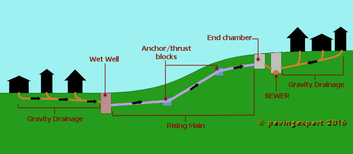
In essence, the water or effluent is collected and directed to a sump under gravity, with pipework laid to a standard gradient, just as would be the case with a regular installation. The end point of the pipework is a chamber known as a sump or a wet well. This is basically a big, leakproof hole in the ground that has sufficient capacity to store the collected water or effluent until such time as there is a quantity worth pumping back up the slope to the nearest disposal point, which is usually an existing sewer.
This arrangement is variously known as 'sump and pump' or a wet well pumping system, or a rising main, and variations thereof (wetwell, sump'n'pump, etc.).
On larger sites where the system is likely to be adopted or is subject to inspection and assessment under Building Control or the local Water Authority, there are specific rules that must be followed which set down requirements for exact construction detail, diameter of pipework, size of wet well, pump requirements, anchor blocks and much more.
The basic premise is illustrated opposite.
Note that the intake of the pump sits at least 100mm above the base of the sump so that it isn't drawing in any silt or detritus that may have found its way into the system.
All the essential detail is covered in the Sewers For Adoption document, which you can buy via this link. Pavingexpert.com receives a pitifully small commission for any such sales, and this helps fund further development of the website.
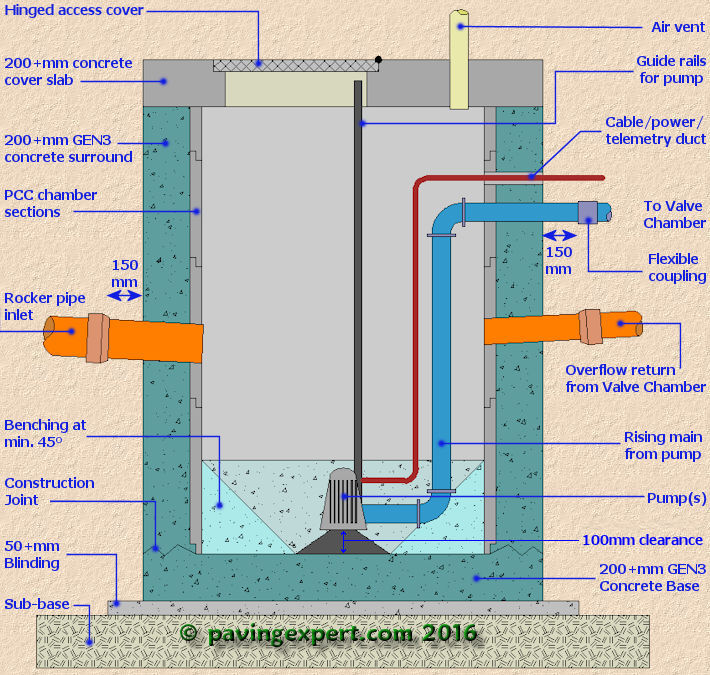
Wet Well Cross Section Drawing:
The basic components of a compliant wet well are shown in this diagram but you are urged to check the latest edition for Sewers For Adoption for fully detailed and up-to-date guidance.
The pipe(s) from the pump(s) will feed into a separate Valve Chamber structure located nearby which, in turn, feeds into the rising main leading to the sewer system.
Sump & Pump for Garden Drainage
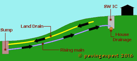
Obviously, full scale wet wells, with the accompanying Valve Chamber and a Control Kiosk, along with sufficient hardstanding to accommodate an effluent tanker is probably a tidgy bit over the top for projects where all that is needed is a bit of garden drainage, so here's a scaled-down version of the same principle....
Essentially, it's an off-the-shelf pre-formed chamber, plastic or concrete, sat onto a concrete base.
Surface and/or ground water from the garden is directed into the sump via the inflow pipe, and it's pumped out again via a small bore outflow pipe, which takes the water to where it can be safely disposed, such as an existing SW chamber or similar.
The pump is a simple, off-the-shelf submersible pump (sub-pump), electrically powered via a RCD-protected supply cable and triggered by a float switch.
Again, it's important that the intake of the pump sits at least 100mm above the base of the sump so that there's a reduced risk of sucking in any silt or detritus that may have found its way into the sump.
As water from the inflow pipe fills the chamber, the float switch rises until it triggers the pump, which then empties the chamber once gain by sending the water via the outflow pipe....and the cycle starts all over again.
In most cases, where the infow is a pipe from a properly constructed land drainage system wrapped within a filtering geo-textile envelope , a silt trap or catch pit between land drain and sump chamber is not essential, but when the inflow is from an older land drain, an unknown source (such as a spring), or contains a surface water component, then a silt trap is a sensible precaution and will protect the pump from accidental damage by sediment (or worse!)

SUDS Pages