Introduction
The work was done in early winter and the ground is heavy clay, neither of which helped with the photography, but the basic tasks involved in the work are shown in the following sequence of photos.
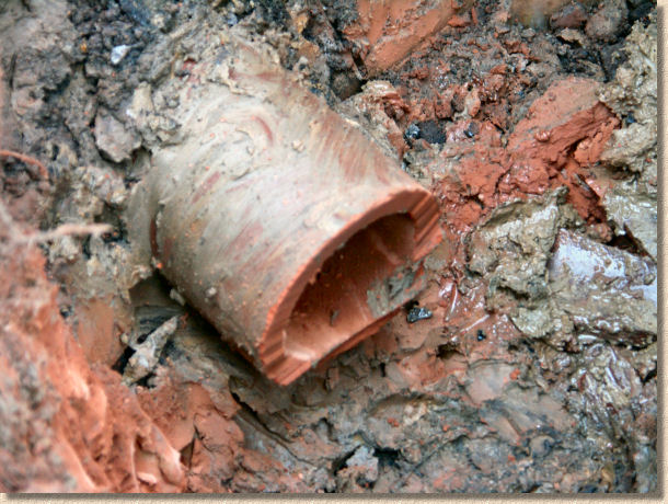
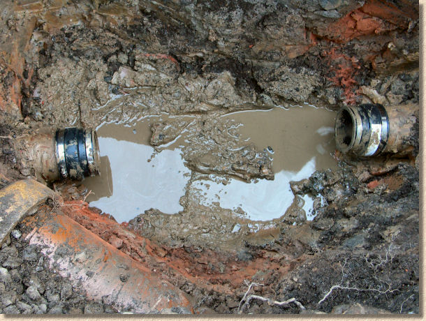
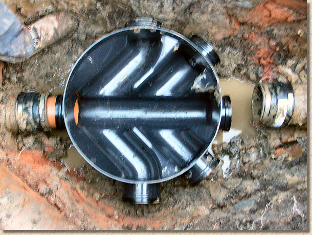
The existing drainage on the site has been located at a depth of approximately 1100mm below surface level. The existing salt-glazed 4" pipeline has been exposed and a full-length pipe laid at a shallow gradient has been identified as the best site for the new IC.
Pipes laid at steep gradients are awkward sites when it comes to inserting these pre-formed ICs, because the pre-formed base has been manufactured to create a minimal fall when the base is installed 'flat', that is, with the upper rim horizontally level in both the transverse and longitudinal directions, and the sides vertically plumb. A sharply-falling pipe would require the base to be installed at an unnatural angle that would render fitting of the raising pieces virtually impossible.
As can be seen from the illustrations above, it's not impossible to insert an IC into a pipeline laid to a steep angle but it does take a certain amount of accommodation to find the correct bends and pipe lengths to ensure a smooth transition between pipeline and IC base, and vice-versa. Whenever possible, ICs are inserted into pipelines laid to gentle gradients.
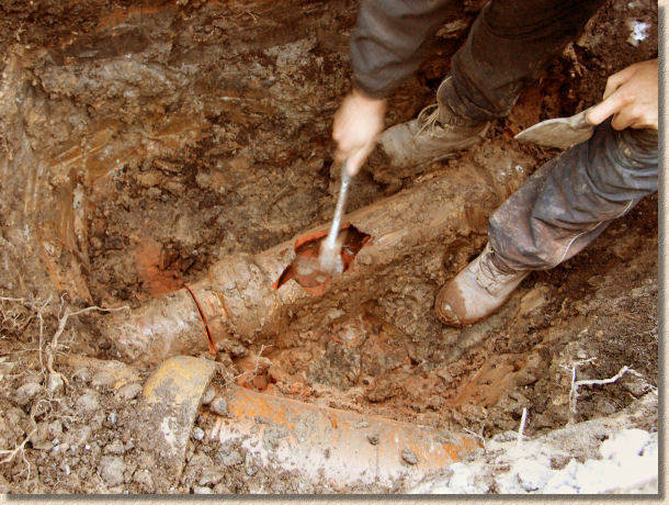
Excavating
Excavation around the pipe involves more than simply exposing the crown and collars: the whole body of the pipe that will be cut out has to be exposed, with 150mm of the material beneath the pipe taken out, usually by a combination of spade and trowel. This is done to accommodate the eventual concrete bed for the IC base which is detailed later. Further, the hole has to be oversize, not just to provide working room, but also to allow 'rocker pipes' to be fitted to the outlet connection and any of the inlet connections that will be used.
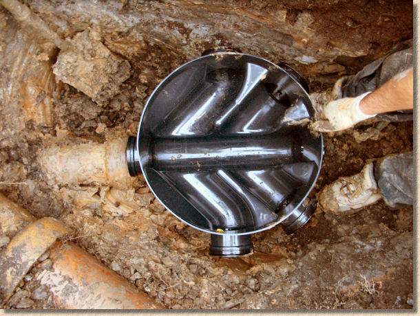
On this project, approximately 225mm was allowed to facilitate fitting the rocker pipes. Note how the base unit, shown in the photo below, is almost the same size as one of these old, salt-glaze pipes, and that one whole pipe plus two collars will be removed to provide adequate space for the IC base and rocker pipes.
Once the pipe has been excavated and exposed, the IC base can be temporarily positioned within the excavated hole to ensure sufficient material has been removed and that there are no obstructions to positioning the base. At this time, the position of the cuts to the existing pipeline is decided.
Once the position for the cuts has been marked onto the existing pipeline, the IC base can be removed and set aside to ensure there is plenty of working room while the cuts are made.
Keeping Dry
Before cutting into the pipe, it is essential to prevent the flow of any effluent or storm water for the duration of the installation. On a foul drain, this might be achieved by simply instructing the property owner not to use the sink or the bathroom until given the all-clear. However, there are situations where it is practically impossible to prevent "input" during the works - it may be that the drain is a common pipe serving a number of properties. In such cases, it's a good idea to place a stopper in the drain at the nearest accessible point upstream of the works, such as an Access Chamber (AC) or an IC. If there is no access upstream, it may be possible to bung in a bung to the upstream pipeline immediately after completing the breakout, but if this is done, it's vitally important to ensure that any such bung can be removed once the IC base is in place.
Cutting
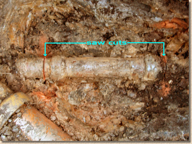
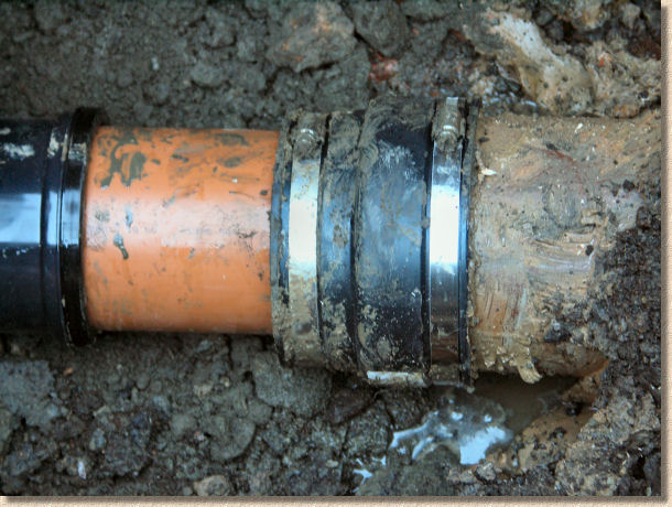
Note how the cuts have been positioned to avoid the pipe collars. This will allow the two collars shown in the photograph to be removed, leaving a stub of standard pipe barrel at both the upstream and downstream ends, to which the new IC base can be connected.
On this project, the cuts are made using a cut-off saw fitted with a diamond blade approved for cutting clayware. Due to the size of a standard cut-off saw blade, it is not possible to cut all the way through the pipe, but the cut should be made as deeply as possible.
By manoeuvring the saw around the pipe as far as is possible, the cut can usually be extended to approximately two-thirds of the barrel, which should be enough to ensure the pipe breaks cleanly.
An alternative strategy involves using a chain pipe-cutting tool. This is a specialist piece of kit but can usually be found in the back of any van owned by a groundworker or drainage specialist. They can sometimes be hired from the usual suspects, but they require quite a deal of brute force to 'snap' the pipe, and the bigger the pipe, the more brutishness is required. Cut-off saws might be dusty and awkward and might not cut to full depth, but you're unlikely to give yourself a hernia while using one to cut a salt-glazed pipe.
Chain Pipe Cutters require the chain component to be fed under the pipe and brought up the opposite side where the chain is hooked onto the teeth of the cutter. The two levers are then brought together (this is where the brute force is required), which tensions the chain, which increases the pressure exerted onto the pipe barrel by the cutting discs, and, with a bit of luck, the pipe snaps with a surprising suddenness, the chain goes loose, and the brutish operative usually lands flat on his arse in the mud.
Despite this apparent awkwardness, pipe-cutters are a superb tool for use at ground level, ie, out of the trench, where they can cut a clay pipe to the required size in a quarter of the time taken by a cut-off saw, and with none of the dust!
Once the cuts have been made, the central section of pipe is effectively isolated from the pipeline and it should be possible to break out the unwanted section without risk of damage to the retained sections upstream and downstream.
A sharp hammer blow to the centre of the unwanted pipe should puncture it, cracking the clayware and collapsing it in on itself. Where the pipeline is a plasticware pipe, a full-depth cut or series of cuts will be required to free the unwanted section.
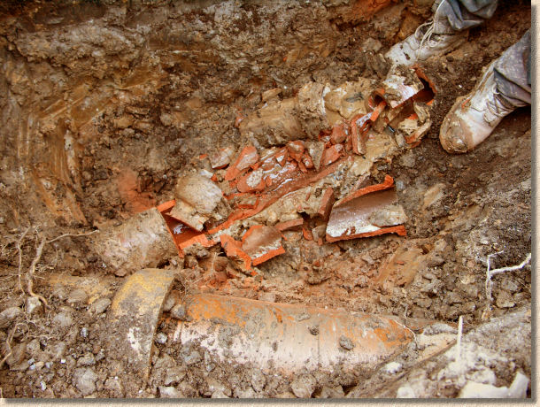
Once an initial breach is created, the remaining unwanted pipe can be carefully broken away using a hammer. Greater care is needed close to the cuts to ensure no damage is done to the pipework on the other side of the cut.
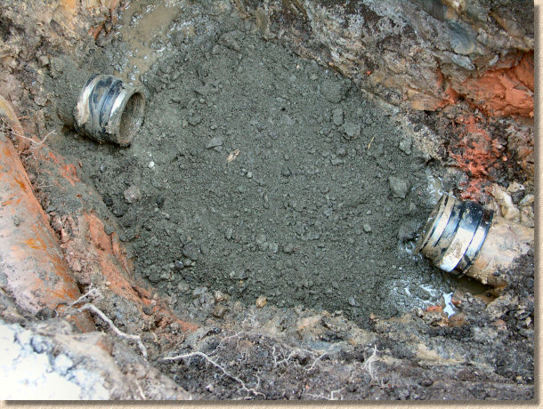
The smashed clayware can be removed and the upstream and downstream stubs cleaned up to ensure they are square-cut and clear of any debris and/or dirt.
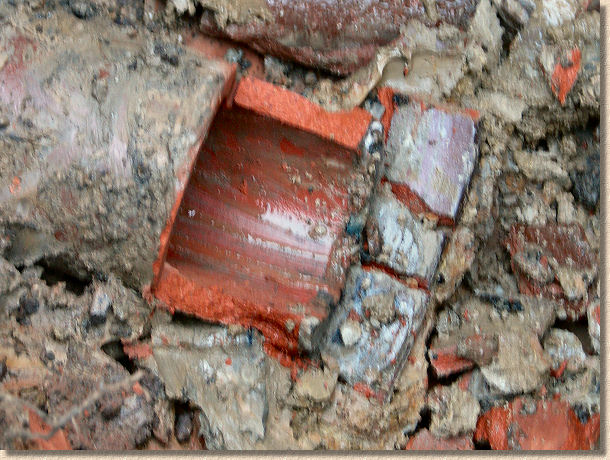
The photograph above shows the stub after removal of all loose material. The original saw cut has not passed through completely and a short section of extraneous pipe remains attached. This piece of pipe must be removed, so a further cut is made, slicing all the way through.
A reasonably 'square' end to the stub is required otherwise a lip or snag may be formed when the IC base is eventually connected, and such imperfections are potential troublemakers - they can cause "effluvia" to become snagged within the pipe, which could result in a full-scale blockage at some later date. So, it may be necessary to re-cut the stub end completely and a smaller angle grinder is often a good choice of tool for such a task as its small size renders it more manoeuvrable than a cumbersome cut-off saw.
So - the stub ends are tidied up and cleaned off prior to fitting the IC base. The adaptor couplings that will be used require a clean surface, so any mud/clay on the outside of the stub end should be cleaned off with water and a towel and it's a good idea to ensure no debris has fallen inside the pipe.
Adjustable Couplings
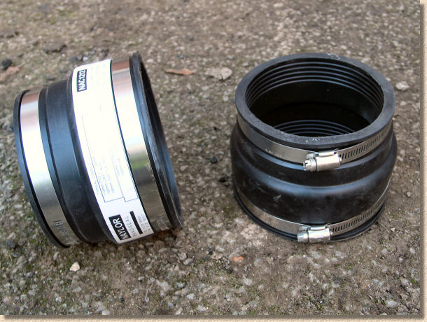
These adjustable adaptor couplings, also known as BandSeal couplings, will be used to connect the new, uPVC pipework and IC base to the existing salt-glazed clayware. There's a significant difference in the Outside Diameter (OD) of clayware and plasticware. Clayware has thicker pipe walls, and so it is not possible to use a standard "straight through" coupling to link the two. These adjustable couplings are formed from a special rubber-like material and the huge Jubilee clips fitted to each end can be tightened up once the coupling is in position so that a firm and watertight seal is formed.
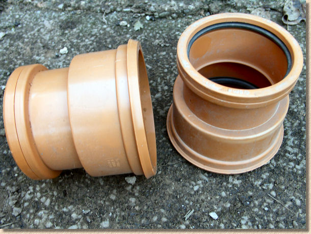
There are non-adjustable adaptor couplings available that can be used to connect uPVC pipes to modern clayware. However, the older salt-glazed clayware, such as that seen on this project, has a slightly larger OD than the modern equivalent, and these couplings would not fit. However, they are cheaper than the adjustable couplings shown previously and should be used if possible.
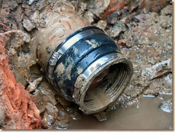
The adjustable couplings can be fitted to the stub ends, but they are NOT fastened tight at this stage.
The weather conditions during this installation made the base muddy and so the couplings are dirty. They will need to be cleaned off prior to final fastening but at this stage, they are simply placed over the stub ends to keep them out of the way.
Preparing the base
The next task is to prepare the IC base.
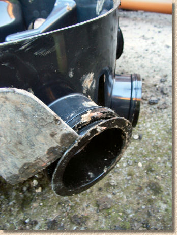
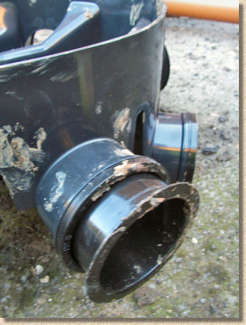
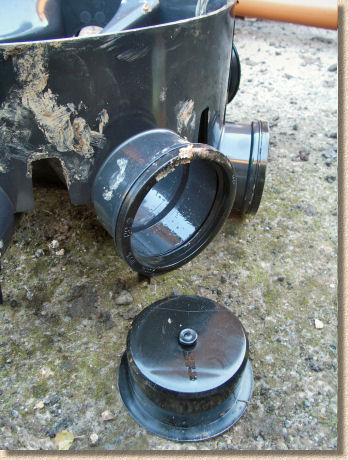
Although the outlet and one of the inlet sockets are 'open' on a new IC base, the four side inlets are closed off by means of a "blanking plug". These prevent spoil and other hard matter falling into the IC once it is in place, but more importantly, they prevent water and effluvia escaping from the IC when it is installed. However, to facilitate the connection of new pipes, the blanking plugs can be removed with a bit of levering to reveal a ready-made inlet socket, into which a pipe or other fitting can be inserted.
Use a large screwdriver, chisel, bolster or even the blade of a spade to lever off the blanking plug from the outside of the IC base unit. Take care not to damage the inside of the socket and to keep it free from grit and detritus. The blanking plugs are usually lubricated with a soap-based product to make their removal easier, and this "grease" can cause all sorts of undesirable detritus to adhere to the socket wall and the rubber sealing ring.
Fit Rocker Pipes
The IC base is connected to the original pipeline via a pair of "Rocker Pipes". These are more than simply short lengths of pipe used to fill the gap between base and pipeline: in manhole construction, rocker pipes are intended to semi-isolate the manhole structure (which is usually a large and heavy concrete or brickwork structure bedded onto a generous helping of mass concrete) from the main pipeline, so that any movement and/or settlement of the chamber will not affect the pipeline - they can be though of as a sort of 'shock absorber'. On a small-scale IC installation such as this, the 'isolating' capability is less relevant than the 'gap filling'.
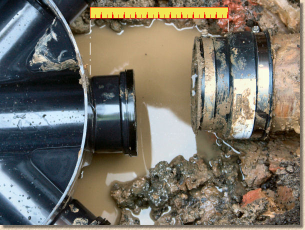
A downstream rocker pipe is created by cutting a piece of pipe roughly 200mm in length. This short pipe is then inserted into the downstream outlet socket of the IC and the base assembly (including rocker) is offered into the adjustable coupling that is still in position on the downstream stub end. This is shown in the photograph below.
The size of the upstream rocker can now be measured.
There's an insertion lip inside the socket of the IC base that is there to prevent any pipe or fitting being pushed in too far. The distance from that point (often identifiable by a ridge on the outside of the IC base) to the stub end pipe is what needs to be measured.
In the photo below, the adjustable coupling placed onto the upstream stub end is still in position, but it can be removed and the gap between the inlet socket and the stub end measured. Allowing 6mm for jointing, the second (upstream) rocker pipe can now be cut.
The second rocker can now be cut to the required size and inserted into the appropriate socket on the IC base back on the surface. All the assembly work is carried out at ground level. It's far easier to force the rockers and other fittings into the base when stood on a level, firm surface than it would be while struggling to maintain ones balance in a muddy hole.
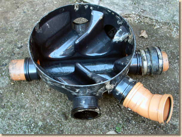
The new pipe connection will enter the IC at the "5 o'clock" position, but the new pipe actually runs more or less parallel to the existing line, and so a slow bend is fitted to the IC base by means of another short rocker pipe. The bend is currently positioned pointing upwards: it can be swivelled around to the required alignment once the base is in its final position.
Notice also that the adjustable coupling from the upstream stub end has also been removed and slipped over the upstream rocker pipe on the IC base assembly.
Placing base
Before the base assembly can be connected to the existing pipe line, a bed of concrete is needed to support the IC base and hold it firmly in place.
The concrete needs to be reasonably strong (C20 equivalent or ST4 ), mixed as a semi-dry, and put in as a layer 150-225mm deep with plenty of spread. This is done to ensure that the completed IC will not sink, settle or move if trafficked by vehicles: even for ICs and ACs installed within pedestrian areas (patios, footways, paths, etc.) a concrete base should be used to prevent any settlement of the IC which would inevitably result in water and/or effluvia becoming trapped within the chamber.
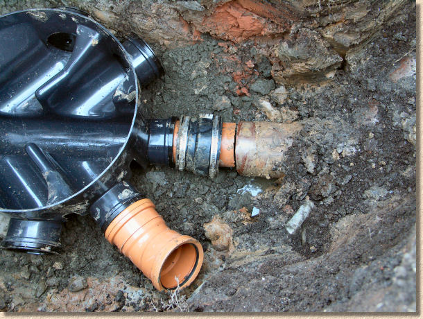
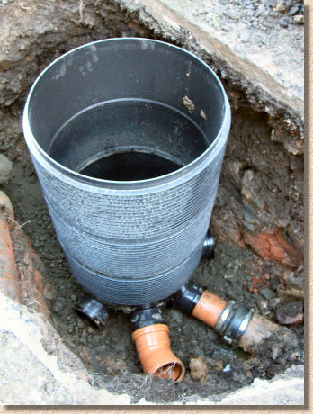
The base assembly can now be sat upon the concrete and rotated to align the rocker pipes with the stub ends. Note the bend fitted to the base to accommodate the new connection - this would normally be protected with a blanking plug, a stopper or simply covered with a placky bag to prevent spoil from the walls of the excavated pit finding their way into the chamber.
The adjustable coupling is currently on the base assembly rocker pipe. The stub end of the original pipeline is cleaned off and the coupling slid over it so that it overlaps both the rocker and the stub end.....
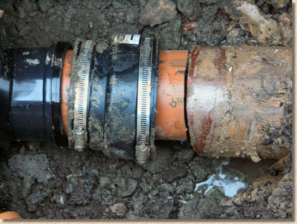
..... and is then tightened up using a screwdriver. Note how the worm gears on the Jubilee Clips have been rotated so that they are uppermost and so easy to access, rather than skewed to one side and awkward to work.
The coupling needs only to be fastened to hand tight. Over-tightening the worm gear will strip the threads and achieve nothing. On pipelines that require testing , it's critical that the rocker pipe and stub end are thoroughly cleaned before fitting the coupling - even a single grain of sand can be enough to allow air or water escape during a test. However, once the coupling is hand tight, additional tightening is unlikely to improve the seal between coupling and pipe.
The process is repeated for the other stub end. On some installations, there can be three or more existing pipes to be accommodated, along with any number of new inlets. The same technique is used regardless of the number of stub ends present. A rocker pipe is always used to connect existing to base.
Finishing off
Once all the adaptor couplings are in place and tightened up, the base needs to be checked for level. A spirit level placed across the base unit so that it is running parallel to the main channel should read as 'flat'. When the spirit level is rotated through 90°ree;, it should still read as 'flat' indicating that the base unit is level and that the raining pieces will be vertical when placed. Should the base not be flat, additional concrete can be packed beneath as necessary to level it up.
Most base units are manufactured with an in-built fall, so fixing them to a position where the spirit level reads as 'flat' will ensure there is some fall within the actual base channel. Don't be tempted to install the base to a fall in the mistaken belief that this is necessary to create fall within the base channel - all this will achieve is a series of cock-eyed raising pieces and a cover that's all skew-whiff!
The raising pieces simply clip onto the base unit via a tongue-and-groove arrangement - the tongue projects upwards so that if the water level within the chamber rises due to a downstream blockage or some other reason, it is less likely to leak out of the chamber.
There is no danger of raising pieces being fitted upside down: the base unit presents a 'tongue' upwards, so the 'groove' end of the raising piece has to face downwards.
For this particular model of IC, three raising pieces create a 1 metre deep section. It is highly unusual for ICs to be deeper than 1200mm - chambers of that depth or greater are typically constructed as manholes, with much stronger walls to resist ground pressure.
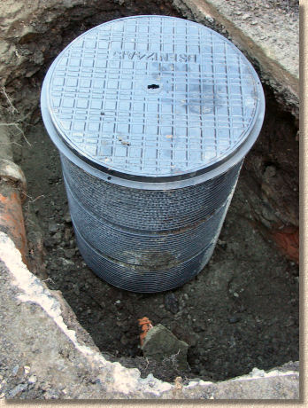
The cover unit comprises a circular frame and 'lid' that simply clip onto the uppermost raising piece using the 'tongue-and-groove' principle yet again. The final raising piece can be sawn down to ensure the cover when fitted, is flush with the paving or ground level.
The new pipework can be connected to the IC as per normal. Additional concrete can be placed around the outside of the base unit to help stabilise the structure, ICs and other chambers of less than 1200mm depth are usually backfilled with granular material and/or the excavated material, ensuring each 150-225mm layer is thoroughly compacted before placing subsequent layers.
SUDS Pages