Beginning with an overview of how specialist kerbs can improve access and user experience of public transport, this page follows the installation of an accessible bus stop in Tameside, Greater Manchester, as a case study which illustrates how the kerbs and associated paving are installed and the benefits that they bring.
Overview from the kerb manufacturer:
The manufacturer of the kerb system used in this case study explains the value of public transport and the importance of improving accessibility:
Since the start of the new millennium there has been a steady increase in bus travel from 3,966 million passenger journeys in 2000/1 to 4,783 million in 2008/9 (Source: Public Transport Statistics Bulletin GB: 2009), a rise of over 20% for the period. However, there is still much work to be done in convincing car drivers to leave their vehicles at home and catch the bus. The major challenge for local authorities is in making local bus travel an attractive proposition for people who have become accustomed to using their cars, and who might subscribe to the opinion that bus travel is a less convenient alternative. This is not an impossible challenge given that traffic congestion often makes urban car travel frustrating and increasingly expensive, whilst many people now see the value of leading a more sustainable way of life; both for their own quality of life as well as for wider society.
Buses themselves bear little resemblance to the uncomfortable vehicles of yesteryear and operators are keen to deliver a much improved service, especially to the less physically able. In the period 2000/1 and 2007/8 the number of public service vehicles with low floors for wheelchair access has risen from 21.3% to 62%. Local authorities also have been working hard to improve the infrastructure which supports bus services, to deliver a much more attractive experience for passengers and other road users.
Greater Manchester offers an impressive example of a conurbation which has embarked on an ambitious programme of improving its bus infrastructure and service. The Greater Manchester Passenger Transport Executive ( GMPTE ), which comprises ten district councils and local operators, has formed a Quality Partnership tasked with delivering a high quality integrated bus system. This scheme is part of a wider Greater Manchester Local Transport Plan (GMLTP), which itself is founded on sustainability and improved movement throughout the city.
Greater Manchester has over 227km of bus routes. Central to the delivery of the system is the development of Quality Bus Corridors (QBC) on which the service will be greatly improved and where buses will be given a higher priority over other traffic. The aim is to make the public transport service more user friendly, pleasant and reliable, and therefore a more attractive choice than the car.
In the region, bus travel makes up 84% of all journeys made on public transport. It is therefore easy to see how important bus travel is to the city. It is also possible to see what effect an improved bus service will have, given that nearly a third of the population in Greater Manchester does not have regular access to a car.
One of the main weaknesses of public transport is the question of shelter whilst waiting for the service to arrive. The QBC network in Manchester features 1,426 bus stops and since the programme started, over 350 new shelters have been installed and more than 1,400 have been upgraded. Improvements to bus stops have been extensive and start with an assessment for location and suitability of use. The assessment of each stop has looked at whether the stop is in the right location, whether the lighting and drainage is adequate, does it provide good quality information, can a shelter and seating be installed (if not already provided), and does it allow for easy access on and off the vehicle.
This last point is of critical importance. Many users of buses will be older, or will have prams, children and bags which can inhibit easy access. Modern buses have evolved over recent years and today's vehicle allows for easier access and more comfortable travel. It is only logical that the bus stop should match this and do its part to make access as easy as possible for all.
The Metropolitan Borough of Tameside has nearly 24km of bus routes which have been part the QBC initiative. Ian Evans, Contracts Manager (Operations) with Tameside Metropolitan Borough Council , explains how the programme has been carried out on stops along the A57, A627 and A635, and how Bus Stop Kerbs have played a fundamental role in improving bus access:
"The programme of bus stop improvements in the borough has recently featured an apprentice team undertaking the work closely mentored by time served craftsman. The apprentices have a wide range of skills, but specialise in modular paving. We feel that it's the best way of working and the apprentices are learning a trade.
Brett Kassel Kerbs have been used throughout to help raise the stops to enable easier access on and off the buses. The kerbs are substantial and the perfect height. The project has also recently seen the use of recycled glass as the paving bedding material and jointing filler, which while not a new idea, the council is keen to see reintroduced."
The advantage of using recycled glass is obvious in that it reduces the amount of material sent to landfill. Tameside has a reclamation centre in Droylsden which features a glass crusher. Ground glass of 8.0mm down is used as the bedding material and 1.2mm as the jointing filler.
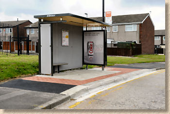
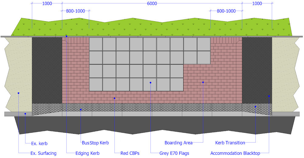
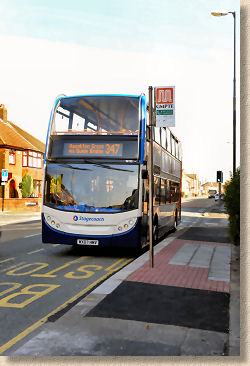
The renovated bus stops feature a blockwork border, E70 flags (450mm square), shelters, signage flag and litter bin. The Bus Stop Kerbs used form a seamless, gap-free link between low-floor buses and the bus stops. This improves passenger safety, especially for the disabled and visually impaired, but also reduces expensive wear and tear on vehicle tyres, substantially cutting overheads for the bus and coach operators.
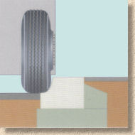
This bus stop kerb is used in over 1200 cities and towns across in Europe, and has become Europe's number one bus stop kerb system. The roadside wall of the kerb guides vehicle into the optimal stopping position leaving a maximum gap of just 50mm between vehicle and kerb thereby maximising safety and service speed, while encouraging the vehicle to not mount the pavement.
Major projects such as the one in Tameside and the Greater Manchester area, illustrate how bus travel is being overhauled to make it more competitive and attractive. The Office for National Statistics says that over 4.7 billion journeys were made by local bus in Great Britain in 2005/06, more than double the number of journeys made by rail. To help bus travel to reach its potential as a major form of public transport, local authorities are adopting strategies similar to that of Manchester. Bus travel is all about the experience and convenience. The more pleasant and convenient the experience is, the more likely it is that people will be coaxed out of their cars. Making bus stops more user friendly may seem only a small part of a programme of improvement, but it is of key importance to the whole experience of bus travel. After all, the bus stop is where people will get their first, but hopefully not last, experience of bus travel.
Installation:
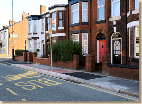
While many new bus stops are constructed using an access kerb system, one of the biggest uses at the moment is as a retro-fit, where an existing bus stop is effectively upgraded by installing the bus stop kerb and renewing the adjacent paving.
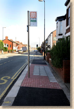
Different local authorities have different layouts for their bus stops, but there is a common theme which involves an access kerb, a tactile surface to indicate the edge and provide increased traction, and usually some sort of demarcation or contrast surfacing to indicate the bus stop area as distinct from the public footpath.
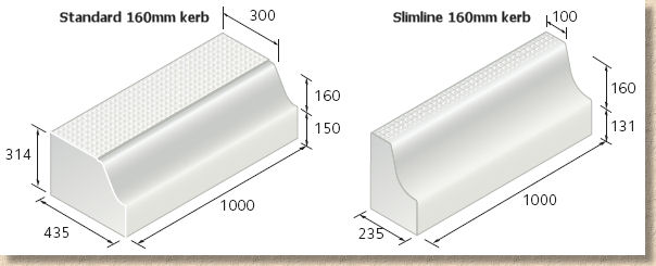
The scheme used for the Quality Bus Corridor in Greater Manchester uses the Standard Kerb with its integral enhanced traction surface, a red concrete block paver used to as a demarcation band, and small element pcc flagstones used as the main surfacing.
The remainder of this case study follows the retro-fitting of a QBC bus stop at a site in Tameside. Installation of the Bus Stop Kerb system is an integral part of the work.
Other schemes make use of a Slimline Kerb, a narrower version of the Standard Kerb which does not disturb the existing kerbline when retro-fitting to an existing bus stop location.
Preparation
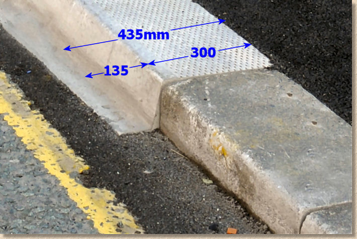
This Bus Stop Kerb system protrudes into the carriageway by approximately 135mm and so it is necessary to create a parallel cut-line approximately 200-250mm from the face of the existing kerb line. This allows adequate room for the new kerb plus a suitable width for accommodation surfacing to make good to the carriageway. The cut is done using a standard Road Saw.
Note that the saw cut extends to include at least one extra kerb at each end of the new bus stop. This allows the first/last existing kerb to be accurately relaid to meet the transition kerb. Consequently, the length of the excavation is approximately 10m...
(1m old kerb + 1m transition + 6m standard Bus Stop Kerb + 1m transition + 1m old kerb)
As the existing footway surfacing is also macadam, this too is sawn, creating a transverse cut that will minimise damage to the retained surfacing while offering a neat joint for the new surfacing.
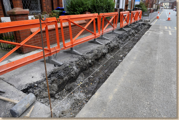
Once the carriageway has been sawn, an excavator is used to remove the existing kerbs and as much of the footway as is deemed necessary at this stage, and to bottom out the trench to accommodate the new Bus Stop kerb with enough space for its concrete bed and haunching.
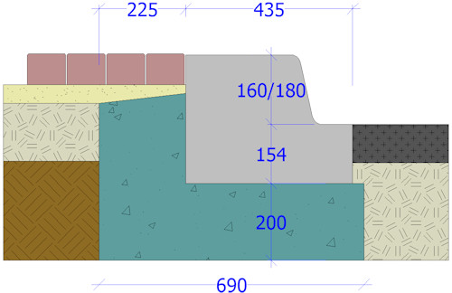
The kerbs need to be laid onto a 200mm deep race of semi-dry (kerb mix) ST4 concrete (C20 or thereabouts) and the race needs to be at least 690mm wide, to allow for a sound 225mm wide haunching, as shown in the cross-section diagram opposite. The trench excavation should be dipped to check the depth is adequate and measured to ensure there will be sufficient width to allow both kerb and haunching to be placed without hindrance.
Bedding
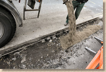
The concrete for bedding is brought to site in a mixer truck. At 690mm wide and 200mm deep, each cubic metre will be sufficient to lay approximately 7 linear metres of kerb.
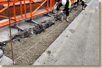
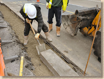
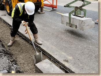
The concrete is typically discharged straight into the prepared trench and is then levelled out using a spade to create a bed that will leave the placed kerb approximately 6-10mm high. A taut string line or laser is set up to establish a guide to both alignment and level. The depth to the concrete bed can be checked by dipping from this line.
Placing the kerbs
The first kerbing task is to re-set the first of the previous kerbs in order to have a starting point for the Bus Stop kerbs that is at the correct line and level.
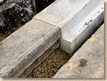
On this highway, the existing kerbs are 300x150mm bull-nosed units laid flat, that is, 300mm wide. Over the many years since these kerbs were first laid, there has been some settlement and so it is necessary to re-set the kerbs that will abut the new Bus Stop kerbs to ensure they are at a suitable level. This is straightforward kerb re-lay work, with a bed formed, the salvaged kerb lifted into position and then it is tapped down to level using the maul.
Due to the depth difference between the old and the new, the bed for the Bus Stop Kerb is significantly lower than that of the older kerbs, so this is prepared once the old kerb is settled into position.
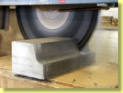
The Bus Stop Kerbs are supplied strapped and wrapped onto pallets for ease of handling prior to laying. For specific projects such as these bus stop installations, the kerbs can be picked at the factory to provide all the components required for each bus stop, with six standard units plus a pair of transitions (RH and LH) packed onto pallets which can then be craned off the delivery wagon at each location. For this project, the pallets were brought out to site on the morning they were to be laid, and off-loaded using the forks attached to a wheeled excavator. The polythene wrapping is stripped off in readiness for the kerbs to be lifted into position, but the straps are usually left intact until the last minute.
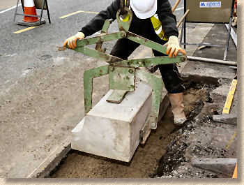
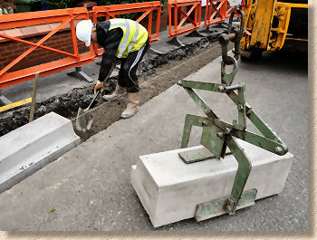
Bus Stop kerbs are heavy: the slightly smaller 160mm high (when laid) unit comes in at a chunky 274kg, so manual handling is completely out of the question. The manufacturer can supply a special Scissor Grab, or one can be hired in for the project. The Scissor Grab is typically suspended from a wheeled backhoe excavator or "Iron Fairy" small mobile crane which lifts each kerb into position, guided by the kerb layer.
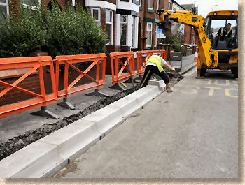
On this project, the Scissor Grab is slung from the back-acter of a wheeled excavator via a rotating shackle as this offers more accurate control and positioning of the suspended kerb without requiring much manoeuvring of the machine on the carriageway.
Note in the photograph opposite that, as the kerb-layer makes final adjustments to the concrete bed, the excavator has positioned itself and lowered its stabilising legs prior to lifting the kerb. The Scissor Grab is lowered over the centre of the kerb, and the lifting latch is released so that when the Scissor Grab is raised upwards, its clamps are free to be pressed firmly against the front and rear of the kerb. Note also how the height stop attached to the grab ensures that the clamp arms are located precisely at the base of the kerb unit, ensuring maximum safety without affecting the bedding.
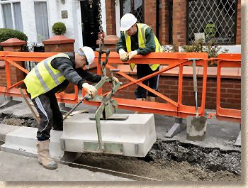
The first Bus Stop unit to be laid is a left-hand transition (a right-hand transition would be used if starting at the outher end of the bus stop). The transition kerb is craned into position over the prepared bed, guided by the kerb layer, who gives the signal to lower the kerb once he's confident it is in a reasonably accurate position.
Once the kerb is resting on the bed, the lifting latch on the grab is closed which keeps the clamps open as the grab is lifted clear of the kerb.
Continue Laying:
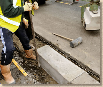
The kerb may require minor adjustment to get it into an accurate alignment. Rather than attempt to use the scissor grab, a large crowbar is used to lever the kerb so that its face is just touching the string line used as a guide to line and level.
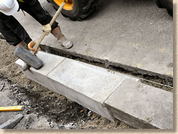
The final task is to settle the kerb to the correct level which is done using the maul . The sheer mass of these kerbs is such that even an almighty wallop from the maul has little effect on the kerb, so it is essential that the bed is prepared with a high degree of accuracy so that only a few millimetres of settlement is required. Often, if the kerb is more than around 10mm high, it is easier to lift out using the scissor grab and re-profile the bed rather than waste time and energy trying to bully it down to level with the maul.
The final task is to check the level of the kerb. With the standard Bus Stop units which will be laid next, the taut string line is used as a guide, but this first kerb is a transition unit and so a long straightedge is required to ensure its line and level are correct.
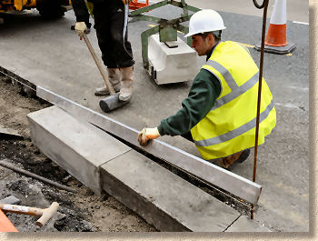
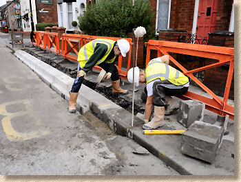
The procedure is now repeated using the standard Bus Stop kerbs. A bed is accurately prepared and then the kerb is craned into position, aligned and settled to the correct level. The kerbs should not be laid butt-jointed, but should have a 2-4mm gap between them. This minimises any risk of spalling caused by adjacent units being in direct contact with each other.
Again, the kerb needs to be pretty close to level when placed as the amount of compaction that can be achieved with the maul is limited. However a good kerb layer is soon capable of getting the bed right every time and so maximising productivity, and with practice the kerbs are laid at a rate not much slower than that for machine-assisted laying of conventional kerbs.
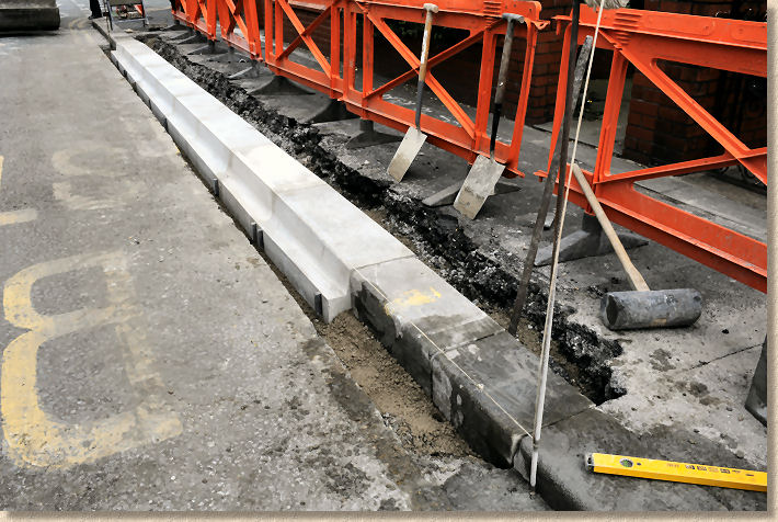
In little more than half an hour, the final Bus Stop kerb is being lifted into place. The last unit to be laid is the right-hand transition that ties in the new kerb line to the existing.
And finally, a salvaged original kerb is laid to link the transition to the existing. Here, the gap to be closed was slightly longer than a single kerb, and so two salvaged units were sawn to produce pieces each longer than a half kerb and close the gap completely.
The final kerbing task is the haunching . Concrete is placed to both the front and the rear of the kerb to secure it into position.
At the front, the concrete fill is kept approximately 40mm below to carriageway surface to accommodate the new blacktop that will be used to make good.
At the rear, it is essential that there is sufficient haunching because the buses use the kerb face to ensure the gap between footpath and bus doorway is minimal. Consequently, significant lateral pressure is imposed upon the kerbs and so a sound haunching is required to ensure they remain in place.
The standard specification recommends at least 225mm width of haunching. On this project, the haunching is allowed to fill the trench so is significantly more than 225mm as it is deemed to make little sense to restrict the haunching to exactly 225mm (using roadform or shuttering and all the additional labour that entails) and then fill the remaining space with Type 1 material or similar. The top of the haunching is kept 100mm down from the top of the kerb to accommodate the eventual block paving that will be laid (see cross-section diagram above).
Assuming 225mm haunch width, and a haunch depth of 320mm, each Bus Stop kerb unit will consume approximately 0.07m³ of concrete, meaning a cubic metre would haunch approximately 13 linear metres of Bus Stop kerb. This 8m installation would need approximately 0.6m³ of concrete for rear haunching, plus approximately 0.1m³ for the front. Combining this with the bedding concrete, reckon on using around 0.22m³ of concrete per kerb (4 kerbs per cubic metre).
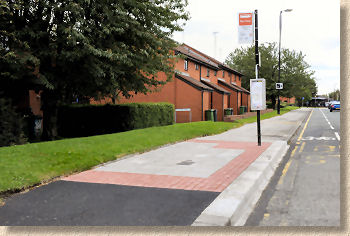
Completion:
Once the kerbing is complete and the concrete has hardened, the surface paving can be carried out. As described above, this comprises demarcation bands of 200x100x80mm red concrete block pavers with E70 grey concrete flagstones . An accommodation strip of blacktop (bitmac) is used to each end of the new bust stop to toe-in with the existing surfacing.
Each bus stop is planned individually. Some may include a shelter, a litter bin or other elements, but all of them rely on the Bus Stop Kerb to provide the simplest and safest access for every passenger, regardless of their personal circumstances.