The next page considers actual installation of the channel and a corner unit, while the last page looks at the finishing touches, such as the end caps and gratings.
Introduction:
The linear channel chosen for this particular installation is the Aco Drive Drain , which has been specially developed for residential driveways and patios, with a range of simple, straightforward fittings, connectors and outlets that make for easy installation for both Contractors and DIYers.
We are grateful to Aco and to KGC Paving of Leigh, Lancashire for their invaluable help in creating this page
Preparation
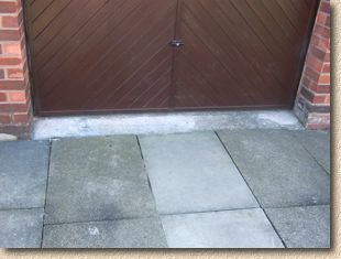
This image shows the garage threshold prior to installation. There is a plain but unattractive concrete fillet between the garage pillars. This fillet is separate from the main garage floor slab and so will be easy to break out. In situations where the floor slab extends from behind the garage door, it may be necessary to leave the concrete in place, although, in some cases, it can be cut out with the aid of a power saw.
Components
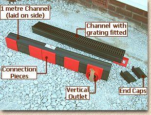
The main driveway itself has been paved with pre-cast concrete flags. If you look carefully, you'll notice the original two strips of the old 3-by-2 flags, with a newer course of metric 900x600mm flags inserted between them at some time. The basic component parts of the Aco Drive Drain system are shown in these photos.
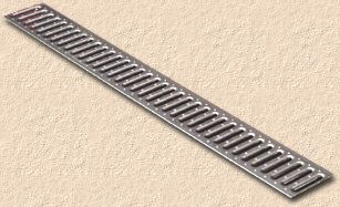
The linear Channel Units come in 1 metre lengths (although 3 metre lengths are also available) and each channel is supplied complete with a Grating unit. For this project, the client chose the black plastic grating shown in the photo below in preference to the galvanised steel grating shown opposite. Both types of grating are perfectly capable of withstanding light domestic vehicles; they have a Class A rating but the black plastic gratings have been shown to withstand loads of 30kN, putting them on the verge of being Class B. Choosing which grating to use really is a matter of personal taste.
On the section of channel laid on its side, 4 individual Connection Pieces are shown, along with a Vertical Outlet unit. There is a further Connection Piece on the other channel, showing how they are placed at the end of each length of channel to join adjacent sections. The Vertical Outlet piece is mounted within a movable fitting, so it can be positioned at any point along the channel to suit the drainage fittings that are available. The Vertical Outlet contains a separate Leaf Guard fitting, which is held in place by a piece of tape during transit.
Finally, there are two End Caps that will be fitted to the ends of the channel run once it has been laid. Not shown in this image is the 90° Corner Unit which we will be using on this project.
Underground Drainage
The Aco Drive Drain system is a surface drain. It collects water from the surface of a pavement and directs it into an underground drain that, in turn, directs it elsewhere, to the main Surface Water sewer, a nearby ditch or watercourse, a soakaway or other suitable SUDS system. Consequently, some underground drainage needs to be installed to connect the Aco Drive Drain to the existing drainage system.
It is good practice to use a fitting referred to as a P-trap to link the Aco Drive Drain to the rest of the drain system. P-traps serve two purposes when used on a project such as this: Firstly, they maintain a sump of water that acts as a 'trap' and prevents iffy odours emanating from the drainage system. Odours are not always a major problem with Surface water systems, but a P-trap, or some other form of trap, is essential if connecting to a Combined System .
The second benefit provided by a P-trap is that it will 'trap' any valuables that may be accidentally dropped into the channel. So, if your wedding ring slips off while washing the car, instead of being sluiced down into the bowels of the earth to be lost forever, it should be caught in the trap, from where it can be salvaged without too much pain.
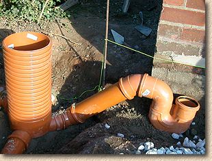
As can be seen from the photo below, a plasticware uPVC P-trap has been installed, and is connected to the existing Surface Water system via a connecting pipe that links into a newly-installed Access Chamber .
On this project, the nearest SW drain lay only a metre or so away from where the Aco Drive Drain was to be fitted, and there was already a junction on this line feeding off to the left to collect SW from the roof of the neighbouring property. Removing this junction and replacing it with a 300mm diameter Access Chamber was the simplest option to form a new connection .
Detailed information regarding the installation of the Access Chamber, the P-trap and all the other bits and pieces of underground drainage are not needed here, but may be covered in a separate page at a later date. For now, it's sufficient to state that the P-trap is positioned in line with the proposed Aco Drive Drain . The actual position of the P-trap, right or left, is not critically important, as the Aco Drive Drain Vertical Outlet unit can be positioned at any point along the channel to suit the P-trap. This gives more leeway to the installer when fitting the drainage, and is one less thing to worry about. However, the level of the P-trap, that is, its height relative to that of the proposed channel does need to be checked. On the photo opposite, a taut string line has been established at the required level for the channel drain.
By measuring on site, or by reading the technical information, it can be determined that the overall height of the Aco Drive Drain is 88mm, which we'll round-up to 90mm for convenience. Once the Vertical outlet unit is in place, this will add another 10-15mm or so, as can be seen from the sketch opposite.
So, when establishing the P-trap, the top of the P-trap unit MUST be at least 90+15=105mm below the proposed cover level of the channel. This is best checked by measuring and then by positioning a section of channel with Vertical Outlet unit over the top of the P-trap just to double check.
Note that this figure of 105mm is a minimum. If it's 110mm, 150mm or even 350mm, that won't be a problem, as the size of the raising piece of pipe is infinitely adjustable, but if it's less than 105mm, it will be impossible to get the channel installed to the correct level.
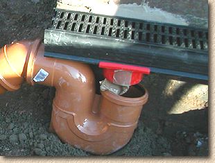
The P-trap has been positioned on a bed of concrete to ensure it's held fast when all the work is complete. The channel with the Vertical Outlet unit slid onto it is presented to the P-trap, and held at the required surface level.
As can be seen, there is an adequate 'gap' between the top of the P-trap and the base of the Vertical Outlet. This can be measured and a raising piece of suitable length cut from a piece of pipe.
We now know that the underground drainage is more or less complete, and that it is compatible with the channels that are to be installed, so, we can move on to the next part of the job....